DIY GoTo Telescope Mount [0] = Introduction and Concept
This is the introduction to a multi part series about building a GoTo system for a Dobson style telescope mount. It should be computer controlled and be able to move to a selected target and also automatically track it. I want to use popular and inexpensive parts known from 3D printing for the mechanical setup, mostly leftovers from upgrade of my Prusa i3 printer.
Links to other Parts
- DIY GoTo Telescope Mount [1] = Altitude Axis
- DIY GoTo Telescope Mount [2] = Azimuth Axis
- DIY GoTo Telescope Mount [3] = Electronics for first Stepper Test
Starting Point
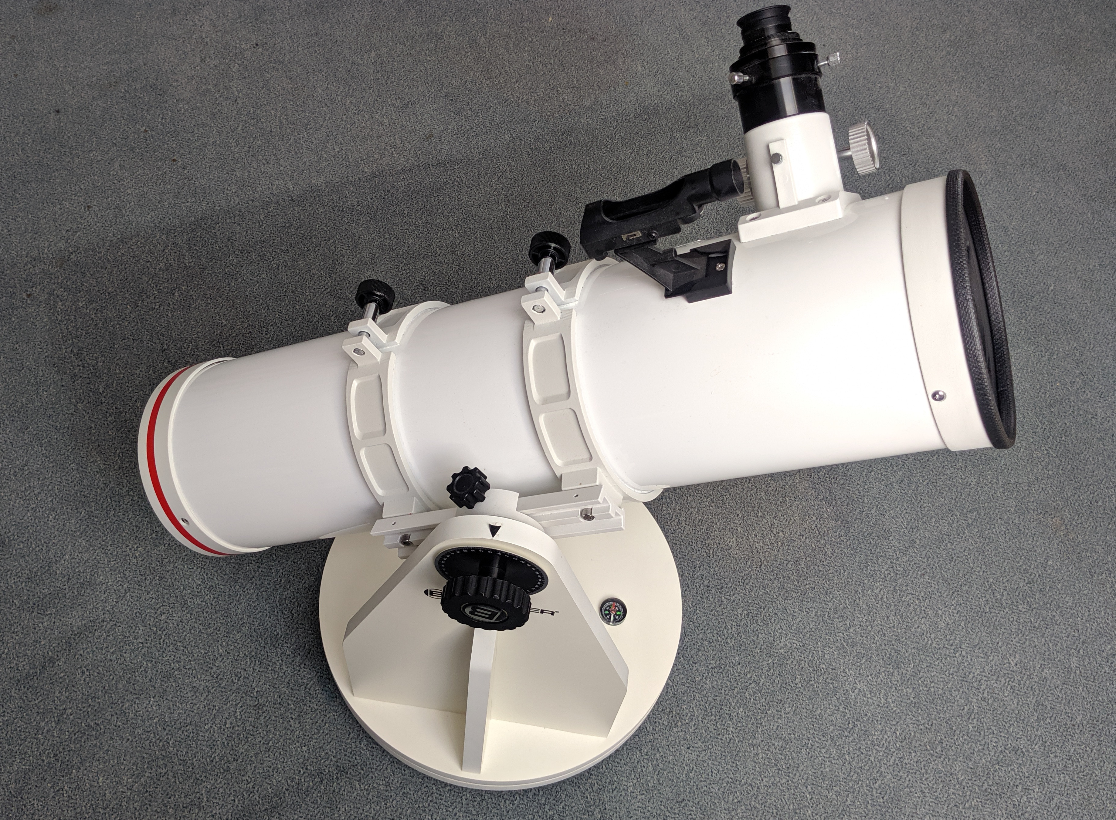
My telescope for this project is a Bresser Messier DOB 150/750, this is a Newtonian reflector with a 150 mm (6 inch) parabolic mirror and 750 mm focal length:
 It includes a simple alt-azimuth “Dobson” mount, made out of wood. For the azimuth (horizontal) axis are two circular sheets of wood stacked in the base one above the other, separated with some sliding pads that allows the whole top to rotate.
The altitude (vertical) axis is also simply a rotatable mounting point, where the optical tube is attached. After loosening the screw the tube can separated from the mount base:
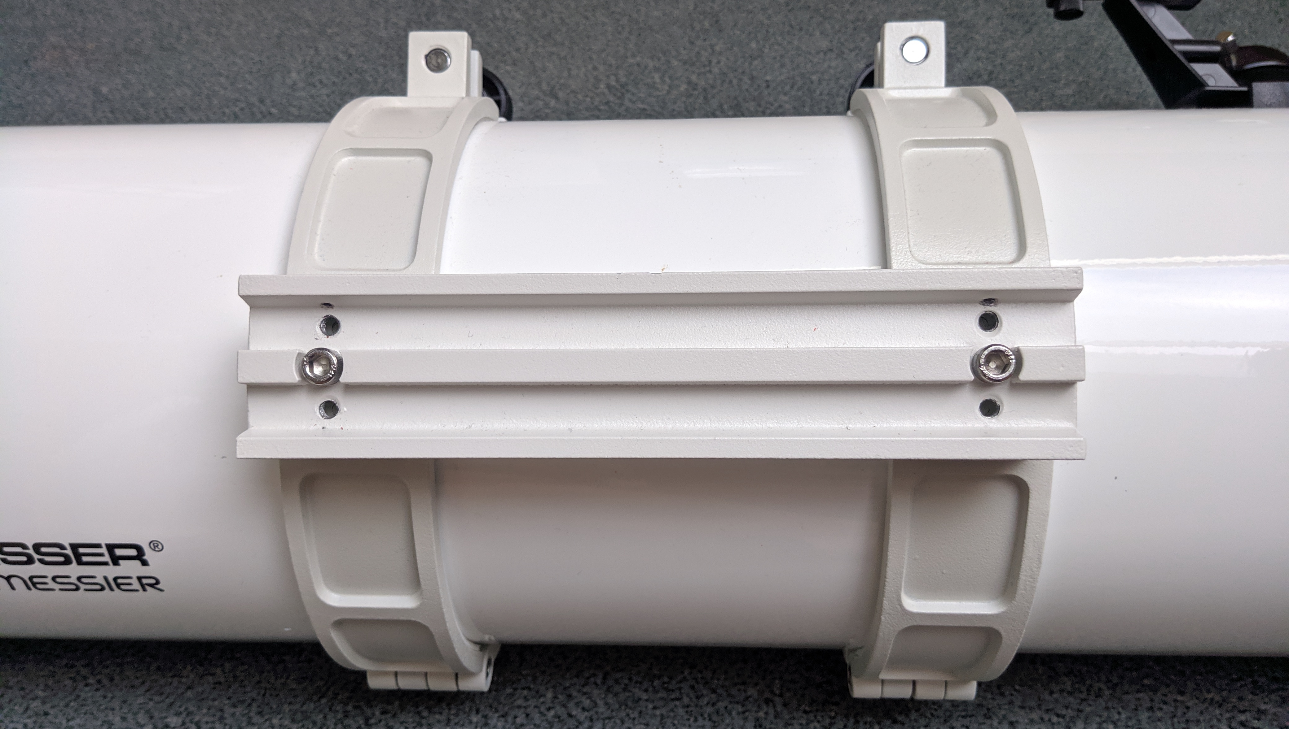 This is a standard GP prism rail piece. Especially the four additional threaded holes are interesting, they contained M5 screws, which are not necessary for stability of the mount, so this is a good place to attach parts for the motorization.
Mechanical Concept
The idea is to keep the whole existing structure and just add motors with minimal additional material. I have seen other selfmade GoTo projects, where the whole mount was replaced with a custom structure. This is really impressive, but also very complex and I don’t have a suitable shop for serious wood working or even CNC machining metal.
I decided to use Nema 17 steppers as drive for the system. To get a suitable reduction ratio a GT2 belt will be used, with an small aluminum pulley on the motor an a large pulley connected to the telescope. All parts (like mounting brackets) should be also 3D printed.
Altitude Axis
Planned here is to construct a pulley around the prism rail, this gives about 200 mm of diameter and allows robust mounting with the M5 holes mentioned above. The stepper motor should be placed on the base plate directly below the rail/pulley and connected through a long belt loop.
Azimuth Axis
Because the base is already a large (about 400 mm diameter) circle I want to directly use it as pulley, only adding a thin profile to get solid grip with the belt. First idea was to simply glue a belt onto it with tooths facing outside. But I noticed quickly that this only works on flat surfaces, if the two layers of belt are bent around a circle the inner circumference would have to be shorter of course and the tooths with the same pitch don’t line up anymore. Only solution is to again print a custom profile taking that into account. The motor has to be protruding above the edge of the circle here.
Electronics and Software
To control the motors I want to use the quiet TMC2208 drivers, connected to an Arduino or ESP32 as main controller. First I thought about developing my own software, but then I found OnStep which looks like exactly what I need.
For usage in the field I need a battery power option. Planned is to reuse 4 cell LiPo battery packs that I already have, they provide 14.8 - 16.8 V. Anything from 12 to 36 V should be fine for the drivers and steppers though. In addition a step down to 3.3 V is required to supply the logic I/O.
As interface I want to use a laptop or phone. Stellarium is a good open source planetarium, that also supports telescope control through builtin plugins.