DIY GoTo Telescope Mount [2] = Azimuth Axis
This post shows the build of the azimuth (horizontal) axis for my GOTO telescope mount.
Large Pulley Profile
CAD Design
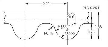
First I tried to copy the tooth profile from the altitude axis pulley model (previous post), but it did not work, because it is not strictly defined, so I made a new new drawing, based on the parameters:
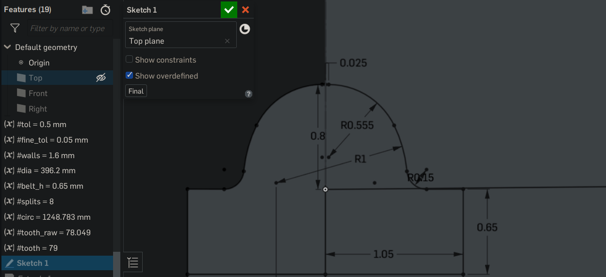
Now fully constrained, with the exact measurements. Still with some tolerance for the 3D printing, implemented through a variable #fine_tol that intentionally makes the teeth a bit wider, here set to 0.05 mm.
Similar to the previous approach the tooth gets repeated with a curve pattern and cut into the part. But now (as already noted in the “learnings” section) I put a valley on the edge, this gives it a less sharp edge and is therefore easier to print.
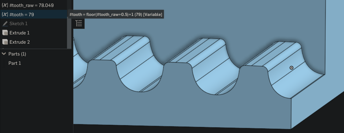 Important is to add one to the teeth count calculation, because half of the tooth is protruding on each end, so effectively one full tooth is lost.
To make it fit on my printer build area I had to cut it again in segments. It is about 400 mm diameter = 1200 mm circumference. Making 7 parts would have worked, but I decided on 8 because it results in round numbers. So each part covers 45 degrees and is about 150 mm wide:
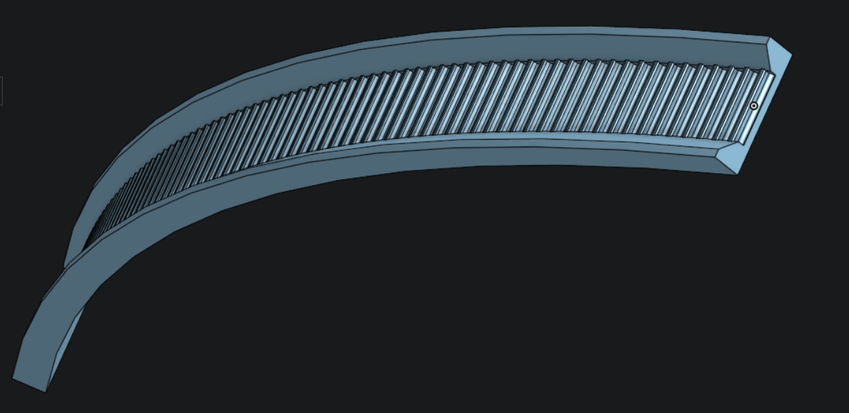
It fits in a circle as virtual assembly from all 8 segments:
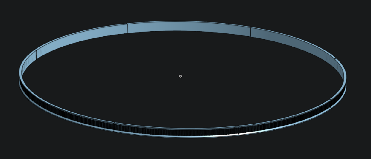 Imagine this ring around the static base plate of my existing telescope mount.
All segments were printed with PLA and 0.3 mm layer height
(two different color because of what I had left).
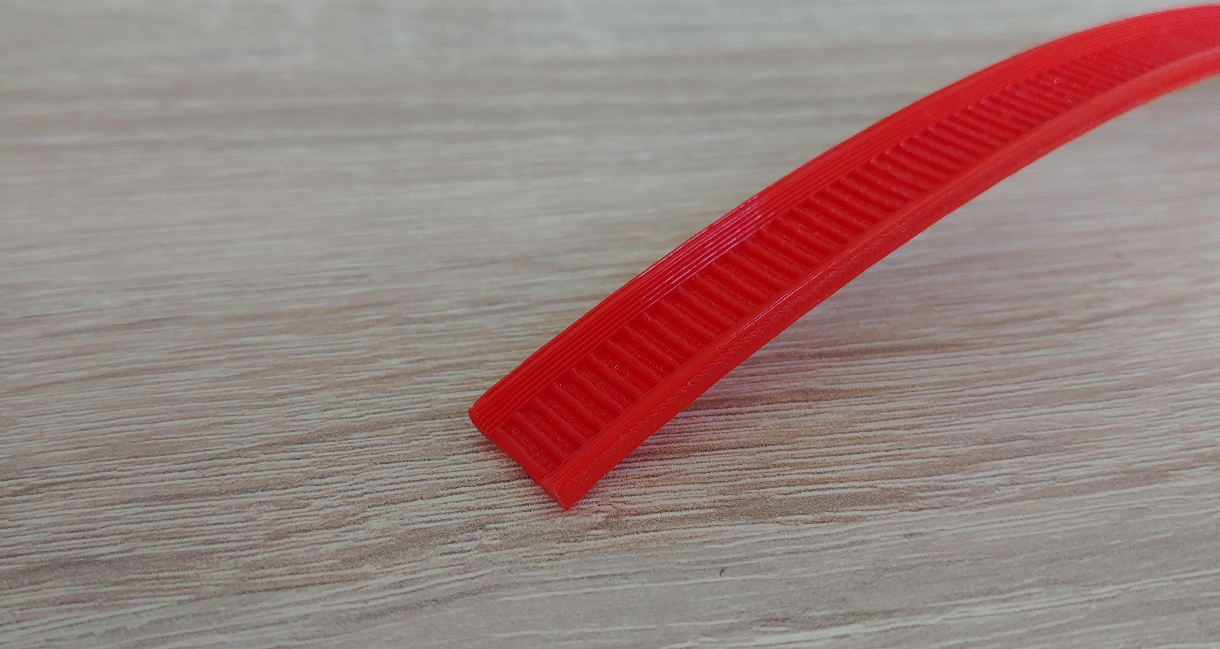
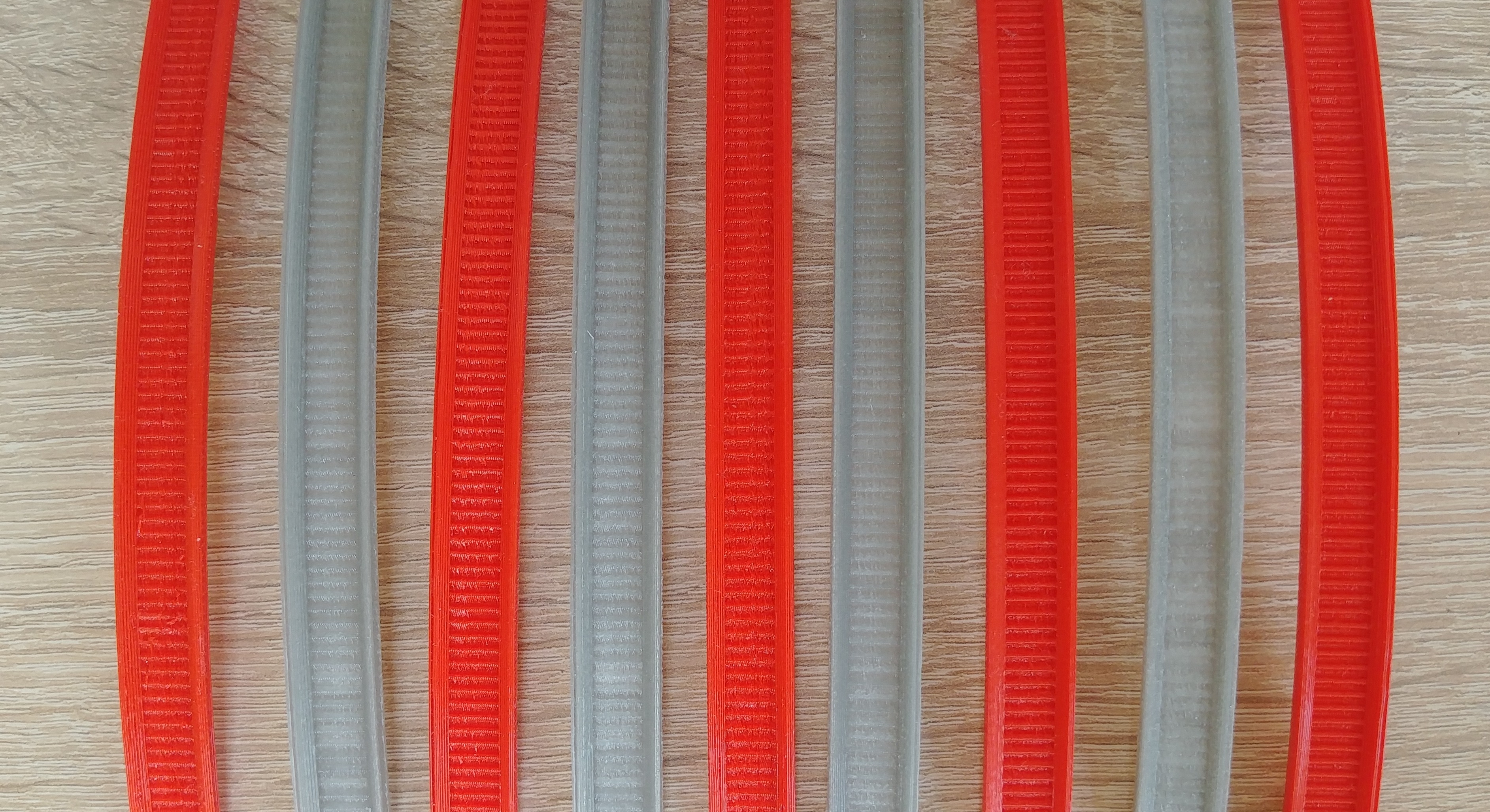 The edges came out much better this time, did not require any postprocessing:
Motor Mount
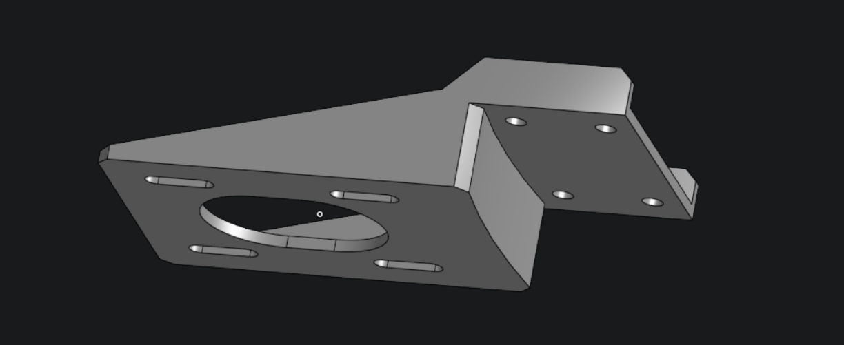
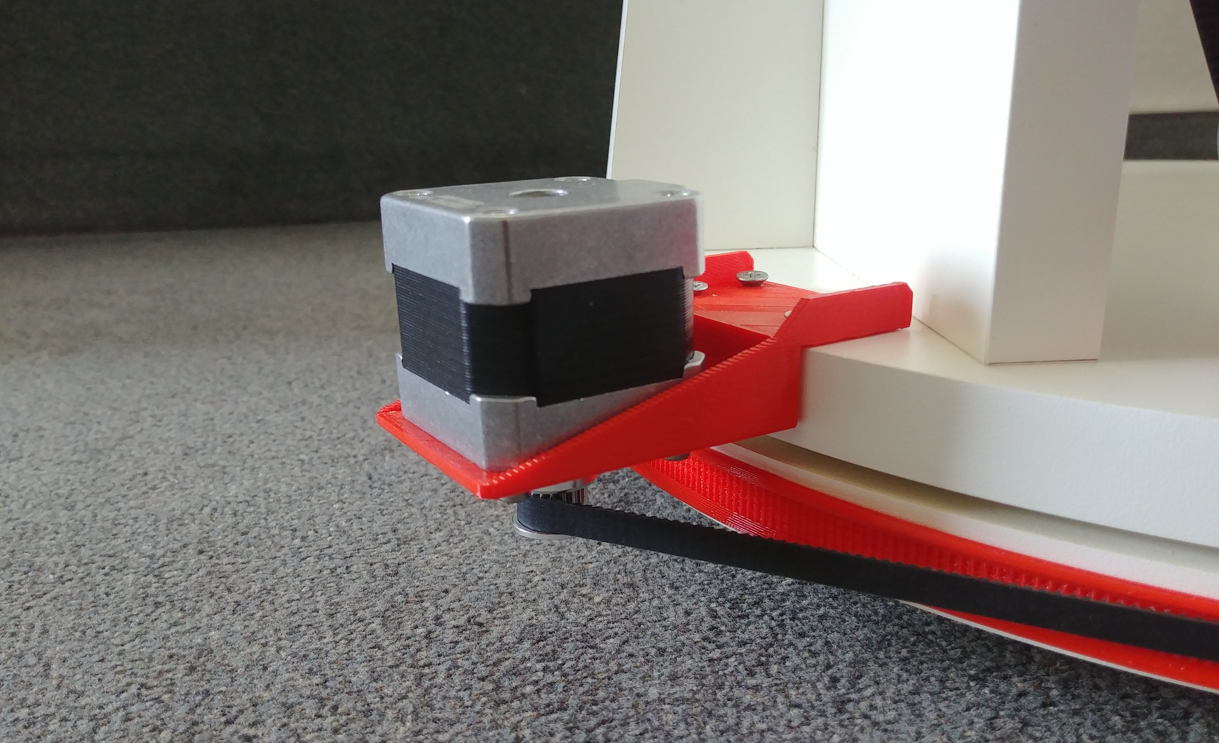
The motor should be connected to top plate of the base. So the shaft points downwards to sit at the same height as the belt, which goes around the bottom base plate.
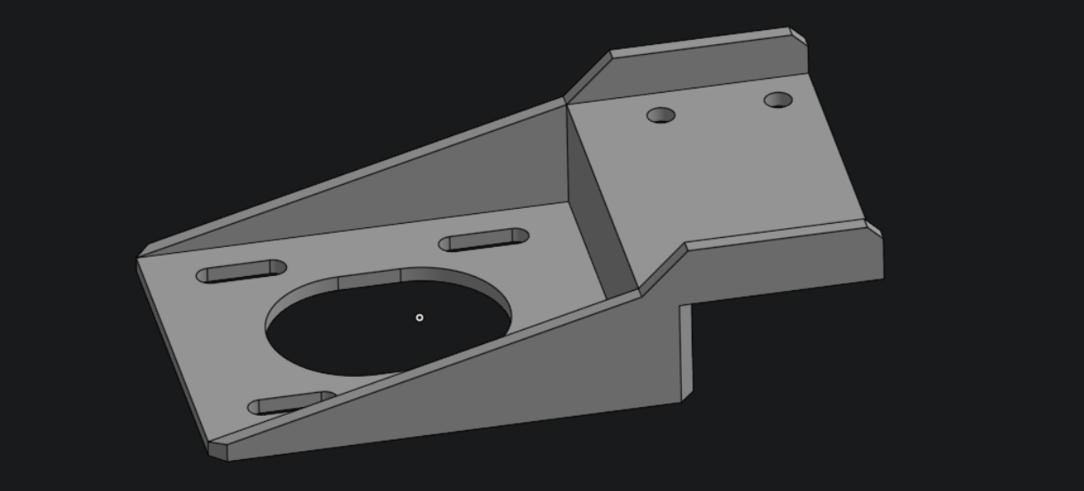
CAD design
The design is not too complicated, I added again some space to slide the motor, which allows adjustment of the belt tension.
It has a slightly curved wall, where it touches the round base plate.
Print and Assembly
I drilled again four 2 mm holes and screwed it onto the plate.
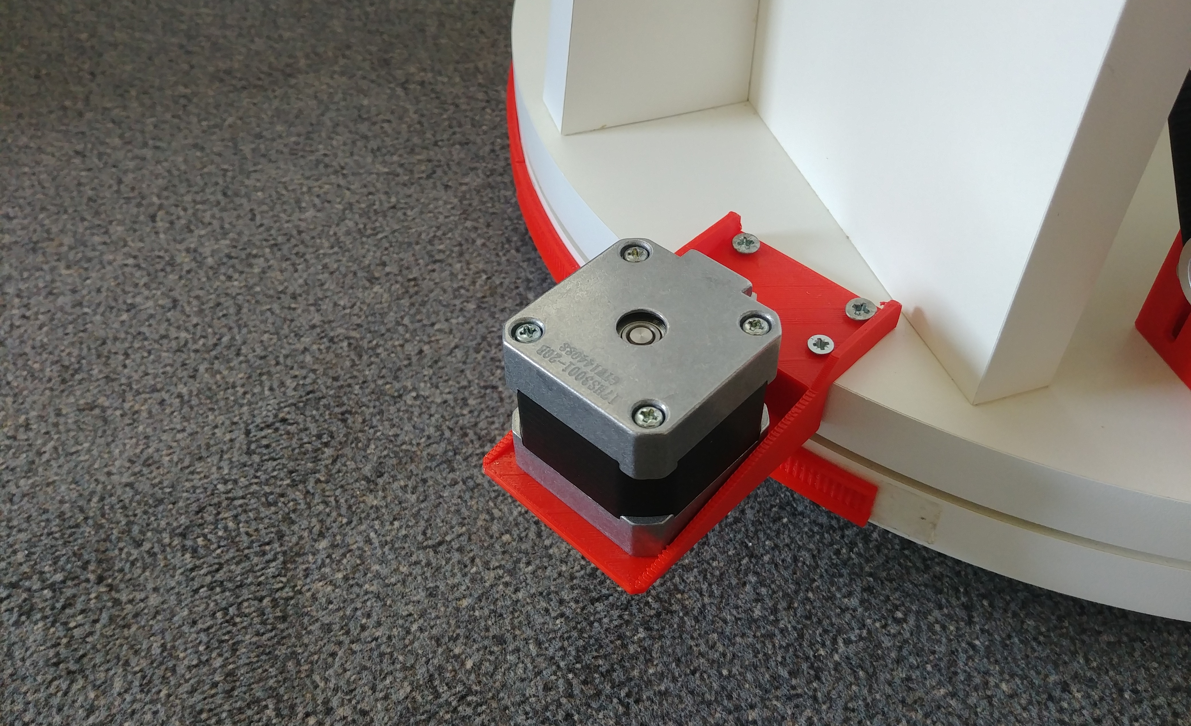 The printed profile is currently only attached by some double side tape. This is enough, because the belt clamps it as well, but I will nevertheless replace it with a more solid glue soon.
Download
As already mentioned I used the online CAD tool Onshape, so if you want to print it yourself you can download it here (see the tabs on the bottom for all other parts).
They support export as STL and many other CAD formats. It should be also possible to copy the project there (needs an account) and adjust all the variables, like diameter, belt size, sections, tolerances… or make other modifications.
Outlook
In the next post I will finally show it in action! With the basic electronics and controller code that I have so far, to test the mechanical setup.