DIY GoTo Telescope Mount [3] = Electronics for first Stepper Test
This is the next part in my telescope series, look at the other posts for more details. In this post I describe how I set up a basic controller to test the mechanical setup.
Electrical Prototype
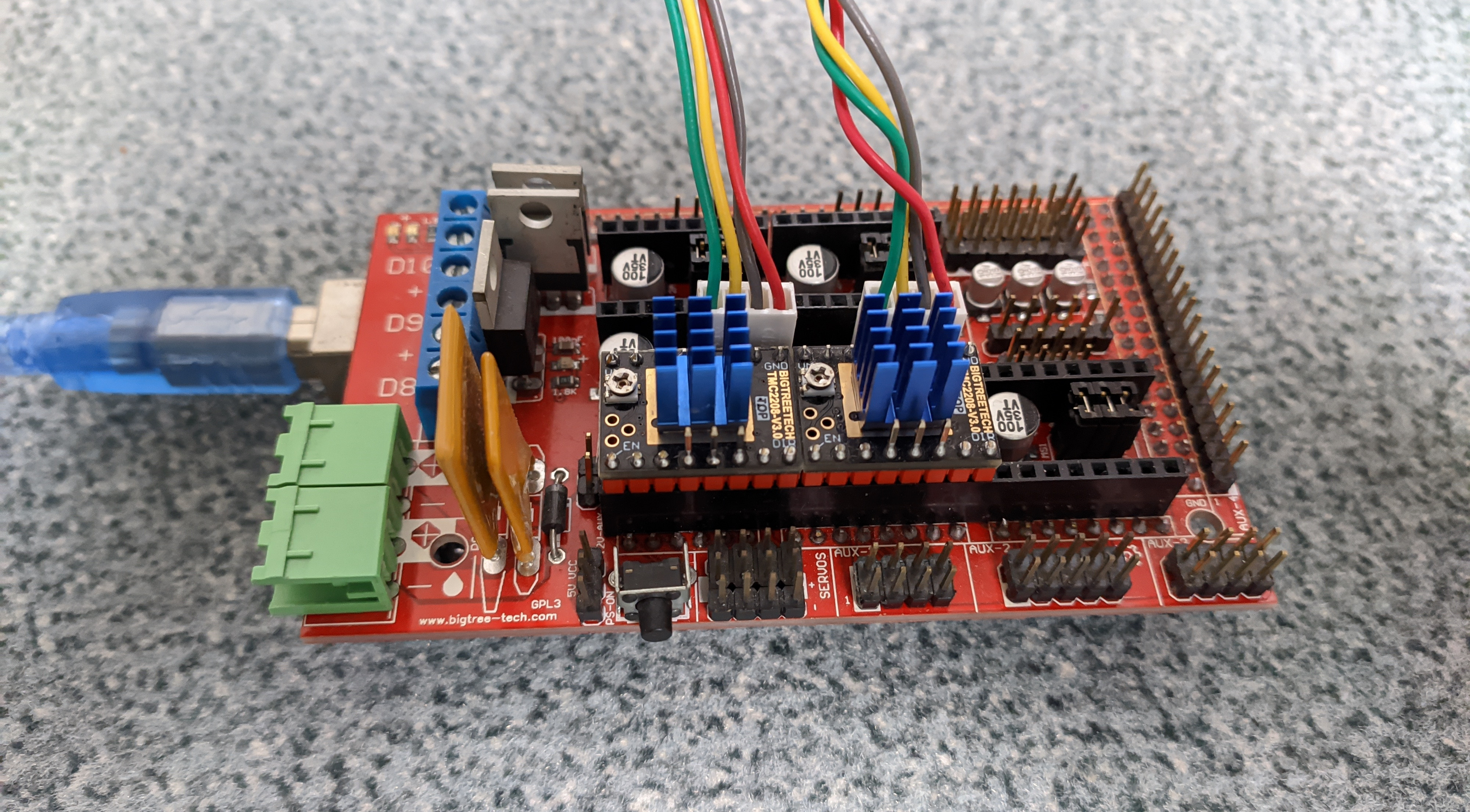
As already mentioned I want to make it as silent as so possible, so I decided to go for TMC2208 in StealthChop mode. First I thought about using breadboard and jumper cables, it is not too complex and the pinout/schematics of my driver breakout modules is available in the BigTreeTech GitHub repo. But because I had a spare RAMPS 1.4 shield from a 3D printer it was easier to just use that.
These TMC drivers are pin compatible to the older/cheaper A4988 or DRV8825. Only noticeable setup difference that is has only 2 instead of 3 pins (or jumper options) for the microstepping, with this layout:
| MS1 | MS2 | Microstepping |
|---|---|---|
| V_IO | V_IO | 16 |
| GND | GND | 8 |
| GND | V_IO | 4 |
| V_IO | GND | 2 |
Where V_IO means pullup to the IO Voltage, +5V from USB in this case. GND is a pulldown (default).
For now I run it with 8x microstepping, no jumpers plugged in, I might change that later. Then I simply inserted the drivers and connected the motors and USB to the Arduino Mega underneath:
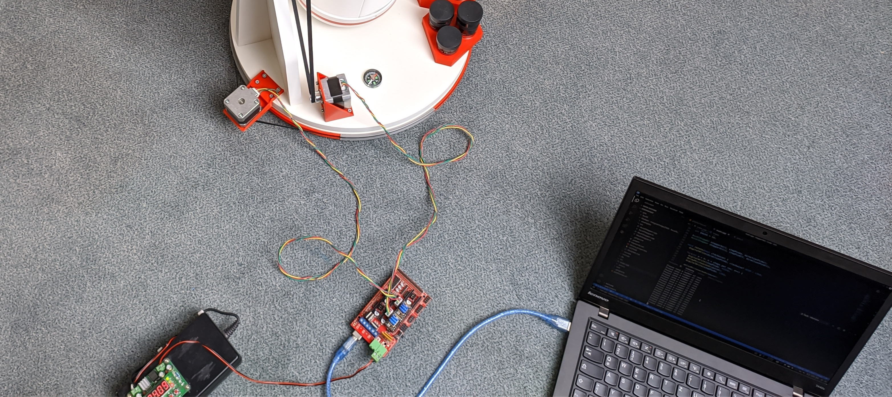
To supply the motors I used a adjustable DC/DC converter (B3603) and laptop PSU set to 24V.
In theory it is also possible to run it on 5V only (section 3.3 in Trinamics datasheet), but it would be less efficient and provide way lower torque/speed.
Overview
Here is everything in one picture:
Arduino Code
Controlling the stepper drivers is really simple, no library required. Basically there is a DIR pin, which must be pulled high or low depending on the direction. Then just switch the STEP pin to execute a (micro)step, with some delays. I made this function to do one full rotation, taking the 8x microstepping into account:
// microsecond timing
int pulse = 1;
int pause = 50;

int microsteps = 8;
long steps_per_rev = microsteps*200;

void rotate(bool clockwise) {
  digitalWrite(directionPin, clockwise? HIGH : LOW);

  for(int n = 0; n < steps_per_rev; n++) {
    digitalWrite(stepPin, HIGH);
    delayMicroseconds(pulse);
    digitalWrite(stepPin, LOW);

    delayMicroseconds(pause);

    digitalWrite(ledPin, !digitalRead(ledPin));
  }
}
Note: steps_per_rev is declared as long, because I experienced overflows when doing math with int here. On 8 bit Arduino (Atmel AVR) int defaults to 16 bit, that is only about +/- 32000. long is 32 bit. Another (probably even better) solution would be to specifically use uint32_t.
This above code works well if there is no load, but with the inertia af the mount (about 10 kg mass) it would only allow very low speeds, otherwise it loses steps when starting a movement.
The solution is to limit the acceleration and slowly increase the speed. I used the AccelStepper library for this. Basic setup code looks like that:
AccelStepper stepper(1, stepPin, directionPin);

void setup() {
  stepper.setEnablePin(enablePin);
  stepper.setPinsInverted(false, false, true);
  stepper.enableOutputs();

  stepper.setAcceleration(steps_per_rev * 0.2);
  stepper.setMaxSpeed(steps_per_rev * 2.0); // Rotation/second
}
It is important to set the enablePin to inverted = true, otherwise it will not run.
Finally to rotate back/forth use stepper.move(steps) or go to a absolute position with stepper.moveTo(stepPos). Constantly call stepper.run() in a loop to actually execute it.
You can download the whole code here. In addition the AccelStepper library must be installed and pins.h with the RAMPS pin definitions added, available at the
RepRap wiki.
Further it could be improved utilizing the UART interface on these drivers, it allows to configure the current, microstepping, etc. through software, like in this TMCStepper example. But for now it legacy (also called standalone) is fine for testing.
Video Demo