DIY GoTo Telescope Mount [1] = Altitude Axis
This post is the first real part of my self made GoTo mount series.
It explains the CAD design, 3D print and assembly of the motorized drive on the altitude (vertical) axis.
Main Pulley
CAD Design
I used Onshape to create a custom 3D model of the pulley. First I measured the length, hole spacing, diameter etc… of the existing tubus mounting rail and saved the values in variables. Then a sketch was built based on them:
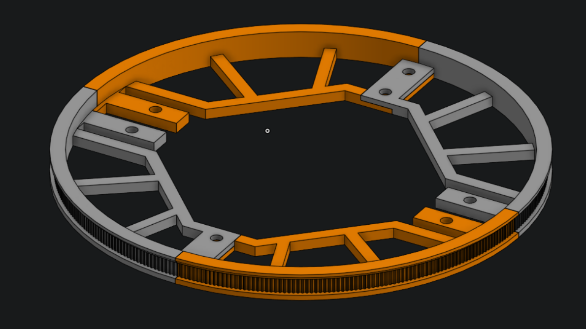
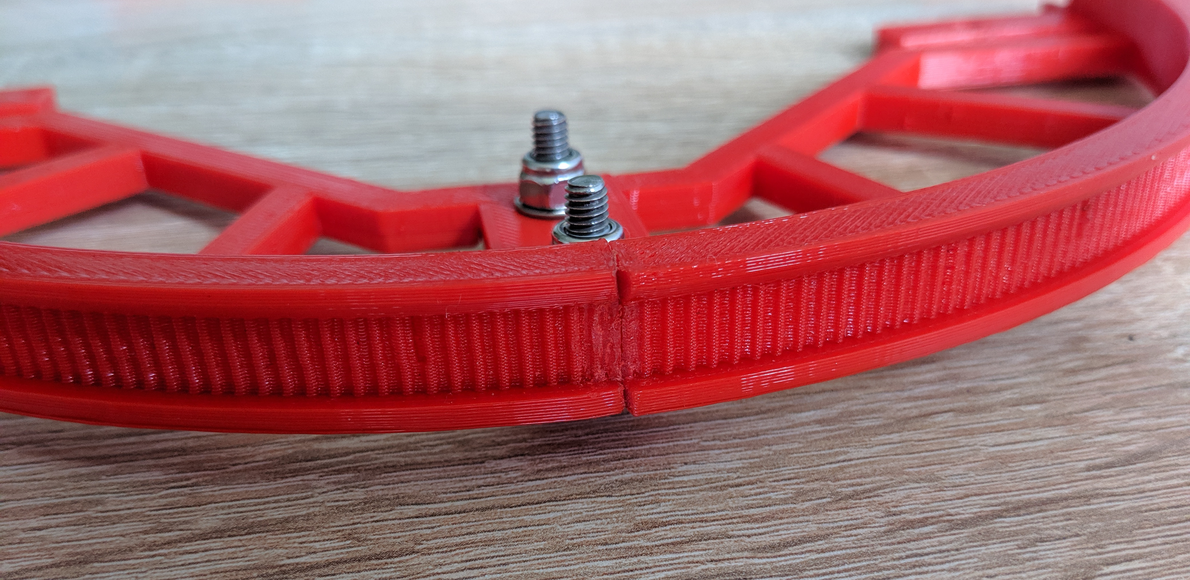
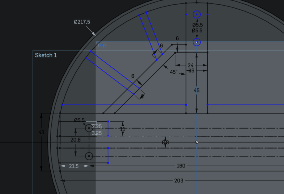 Because of the slightly smaller than 200x200 mm effective build area from my old Prusa i3 printer it was not possible to make the whole pulley in one piece, so I split it into four pieces and added holes to join them with screws afterwards.
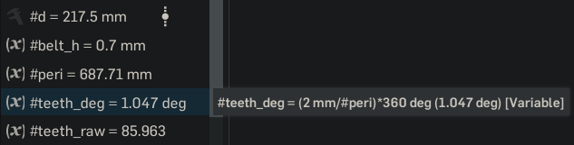
The rail length is only 200 mm, but to allow the edges to fit into the circle, it has of course a bigger diameter. I need the diameter to calculate the correct teeth spacing to fit the GT2 belt, which has 2 mm pitch, so I installed a FeatureScript plugin that can measure parts and create variables. From that the tooth angle and count are calculated for the next sketch. To get a close to integer count (of 86 teeth per quarter circle) I adjusted the base width to 203 mm.
I made the profile loosely based on the GT2 belt definition, adding 0.1 mm tolerance where I saw fit:
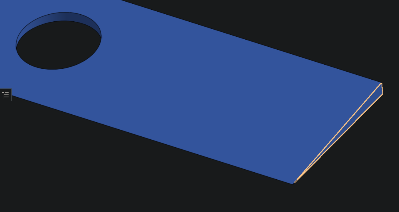
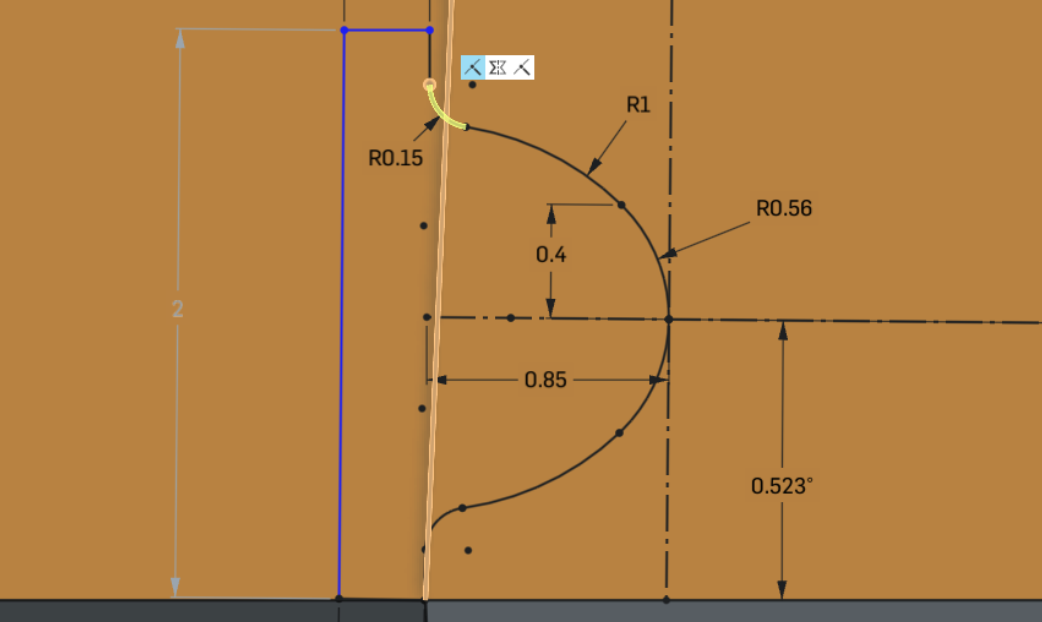 Notable here is that it looks like the one side is not on the circle outline, I checked the constraints and it is actually on the line, but Onshape renders the large circle in a low resolution, making it look like a straight line. This is only a optical issue, the exported model is fine.
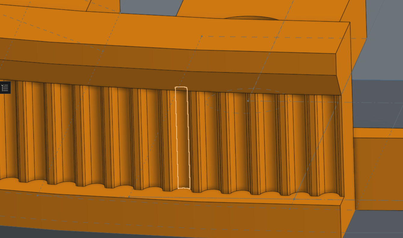
After a circular remove pattern this is the resulting belt profile:
Tests and Fixes
In Onshapes assembly tool the whole pulley seemed to fit fine:
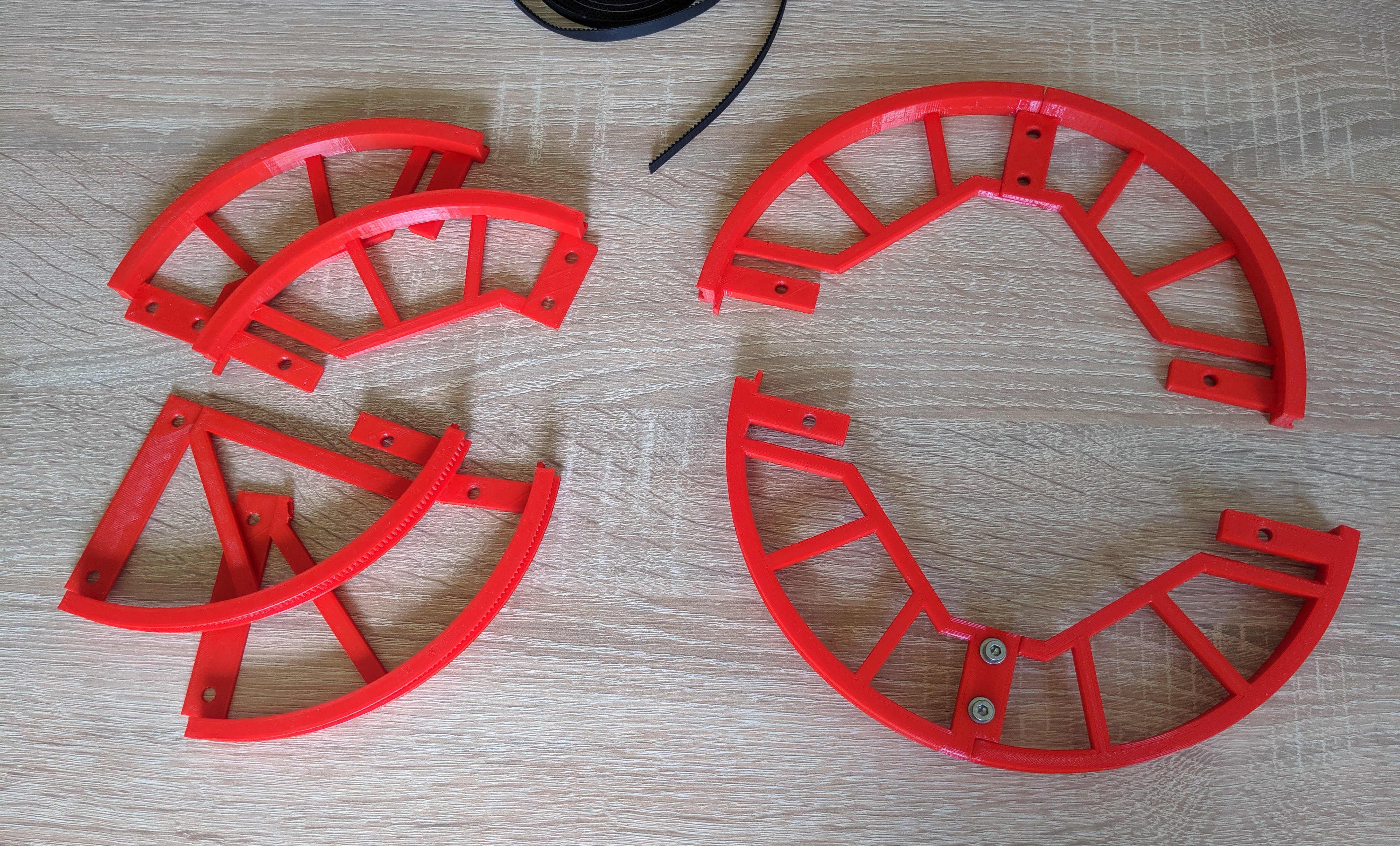
So I proceeded to actually printing the parts. It needed a few tests and adjustments to get the tolerances right, especially where it interfaces the rail, after 4 iterations I was quite happy with the result:
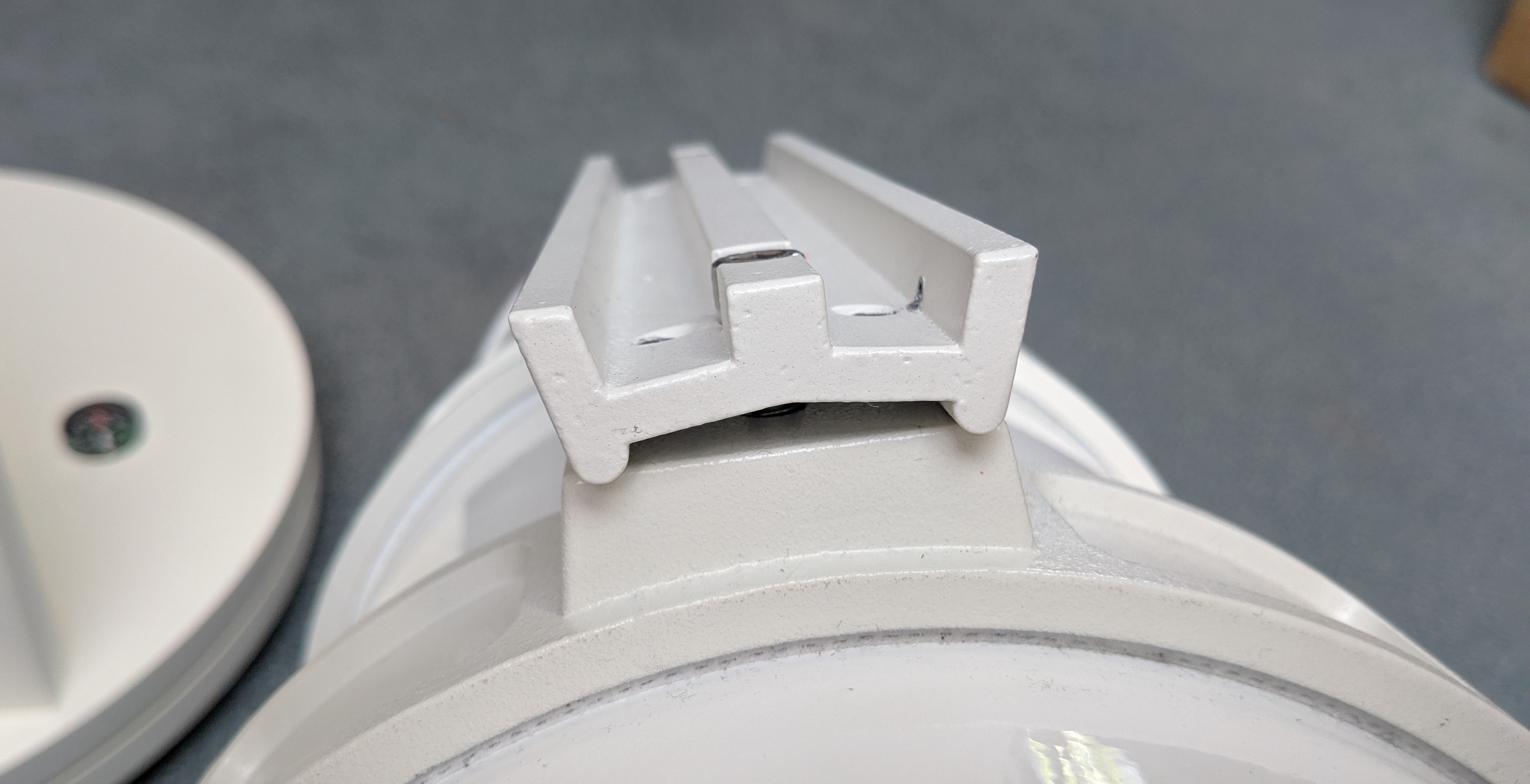
Following I began to tighten the screws for the first time on the rail and noticed that the pulley gets crooked.
This is because the rail bottom is also slightly skewed inside:
 It is about 1 mm deeper on the sides, measured from the flat top. I did not want to print all parts again, so I quickly made some wedge shaped spacers, that are also secured through the screw:
Assembly
After closer inspection I saw some things that required cleanup. The Teeth on seams are cut in half, so there is a quite fine an sharp edge and this resulted in some edge bulging, which I had to scrape off to produce a good belt fit:
 In addition I sanded the surfaces that touch other parts a bit.
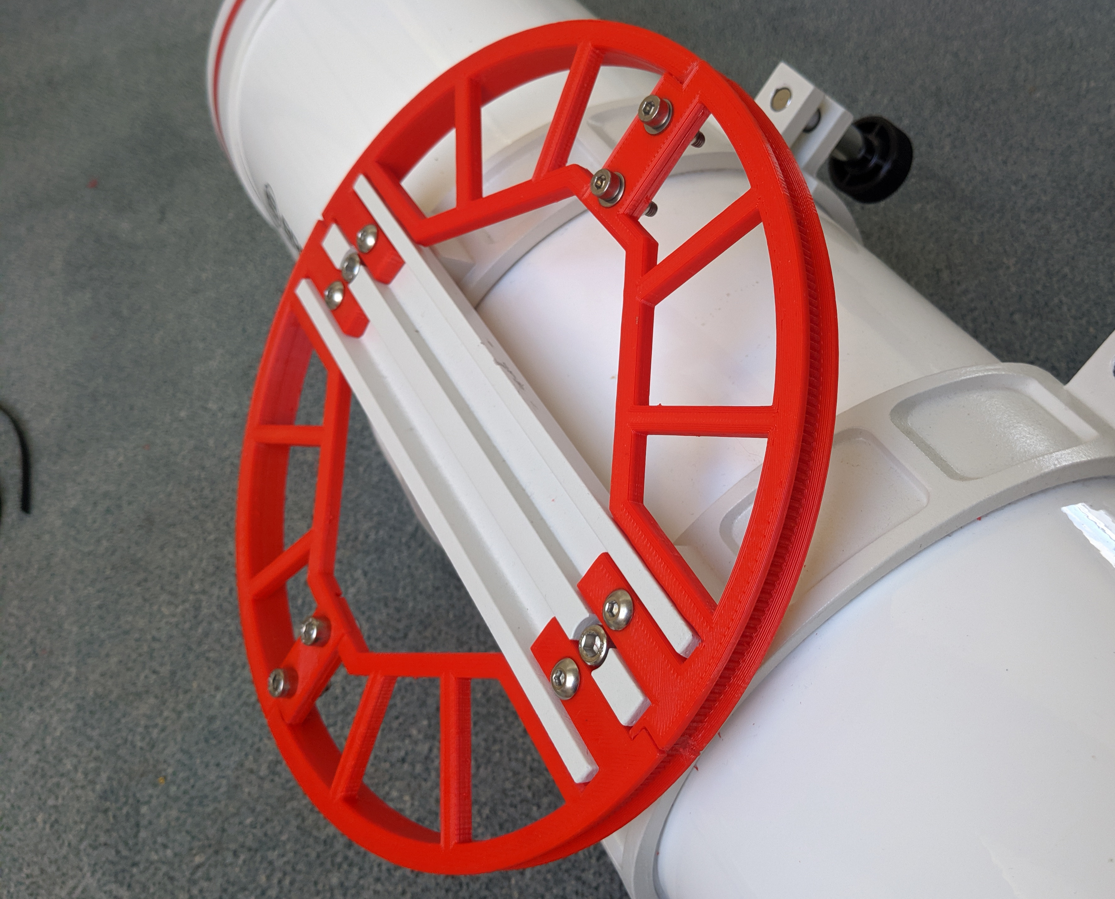
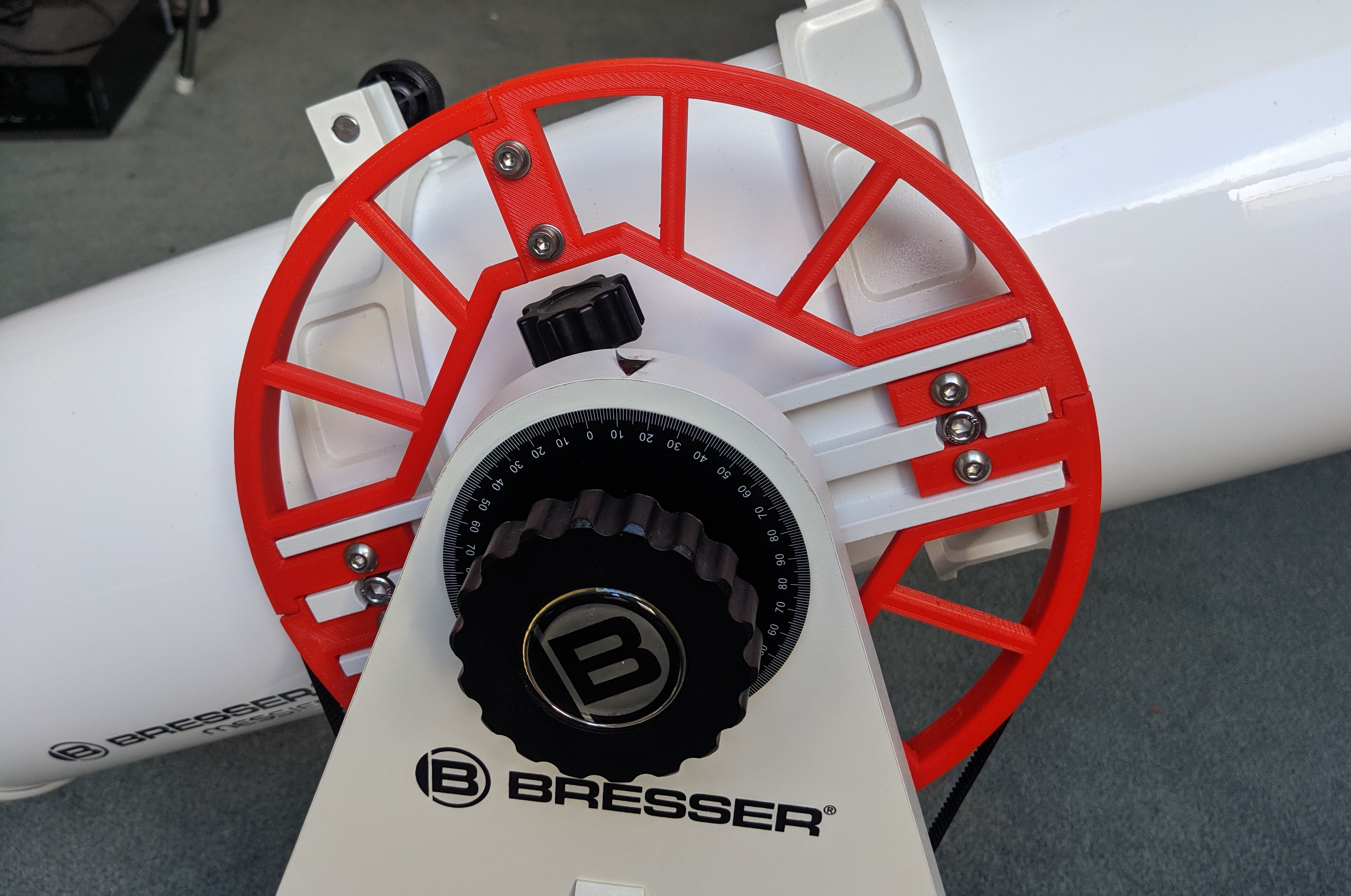
After all it fits nicely on the mounting rail:
Small pulley
Motor Mount
Mounting the motor is done with a pretty simple bracket on the base plate. In CAD:
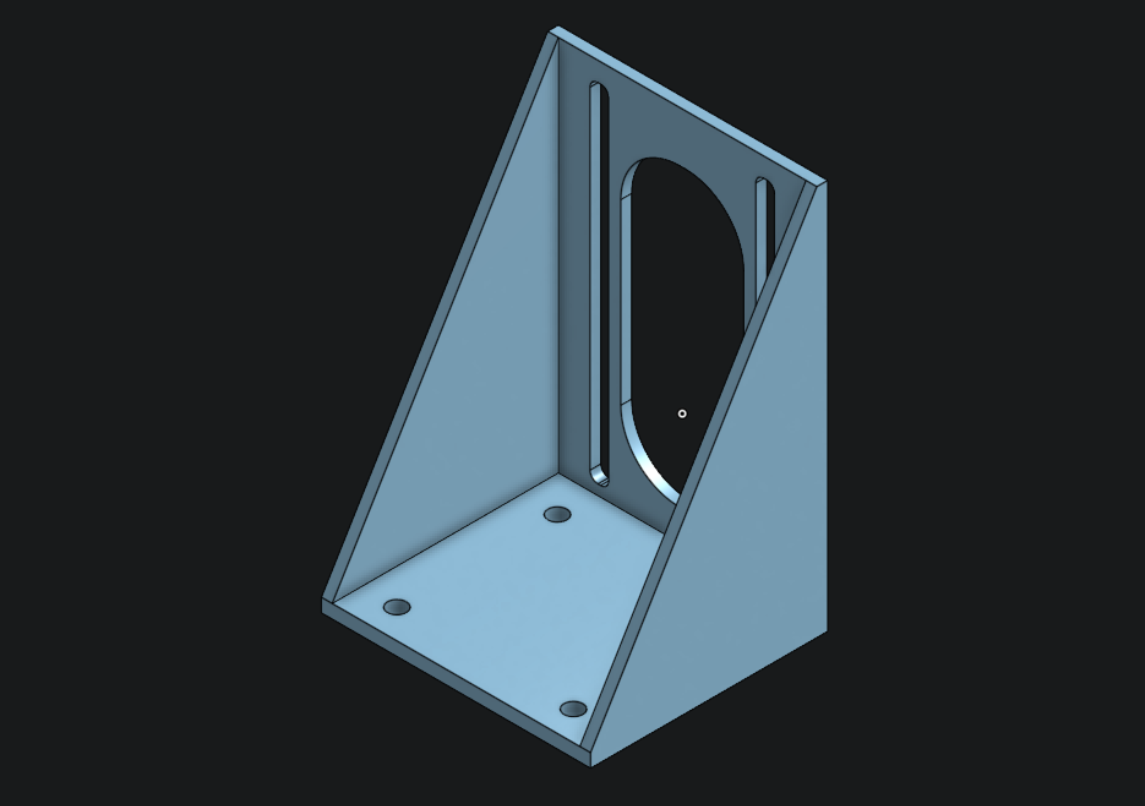
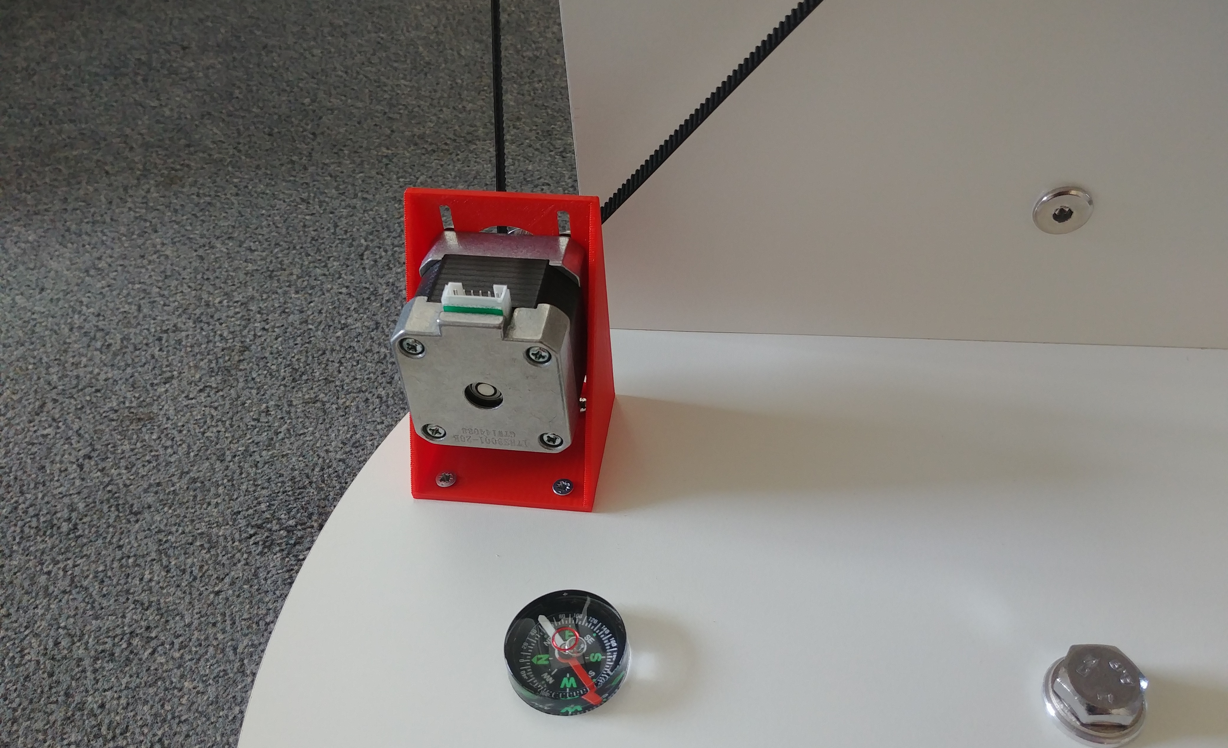
It has long slots, which allows different positions for the motor, so it can be used to produce an adequate belt tension. Printed and assembled it looks like that:
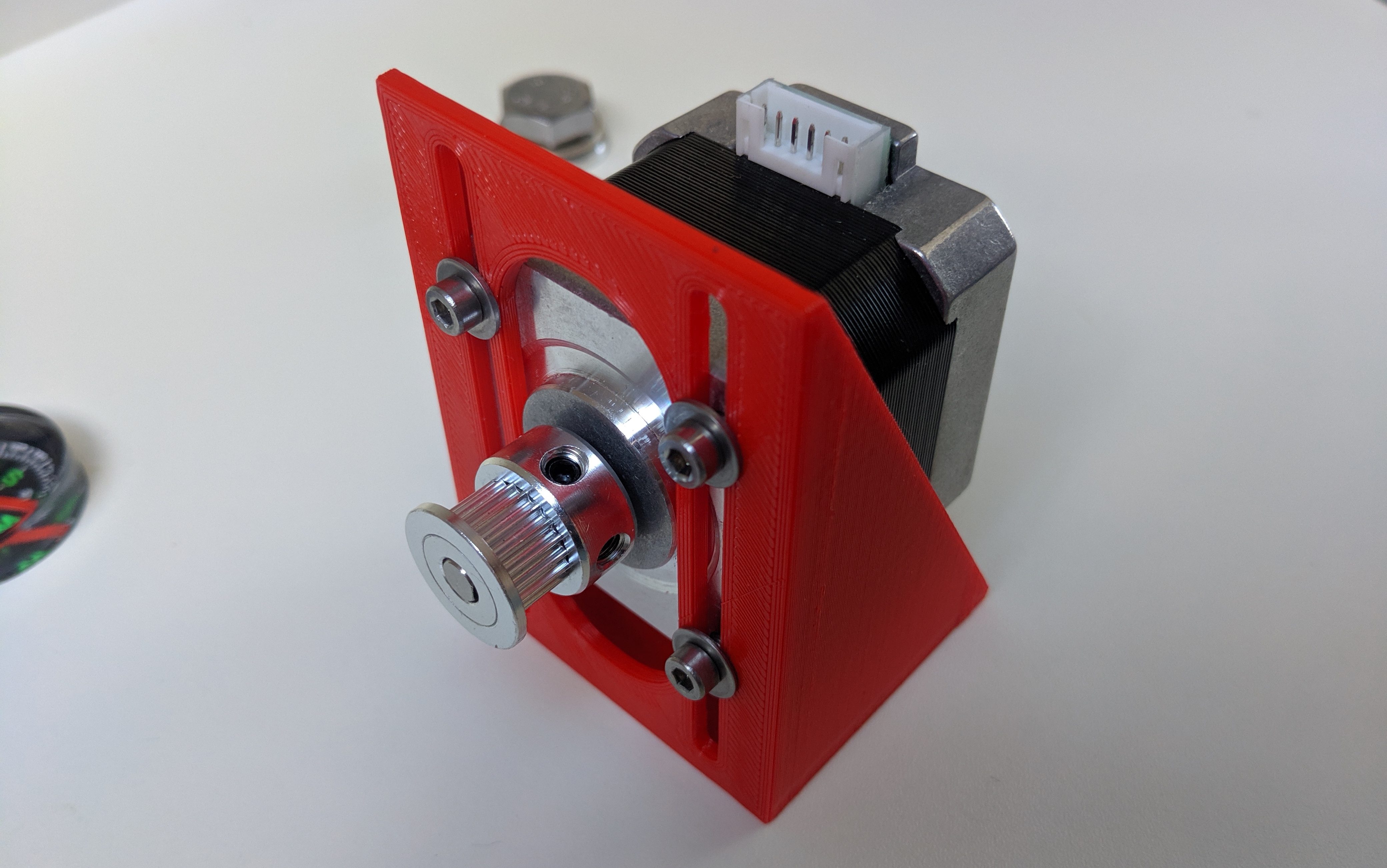 As small pulley I use a standard 20 teeth aluminum part. Combined with the large custom 430 teeth pulley it creates a tranmission ration of 21.5.
Final Assembly
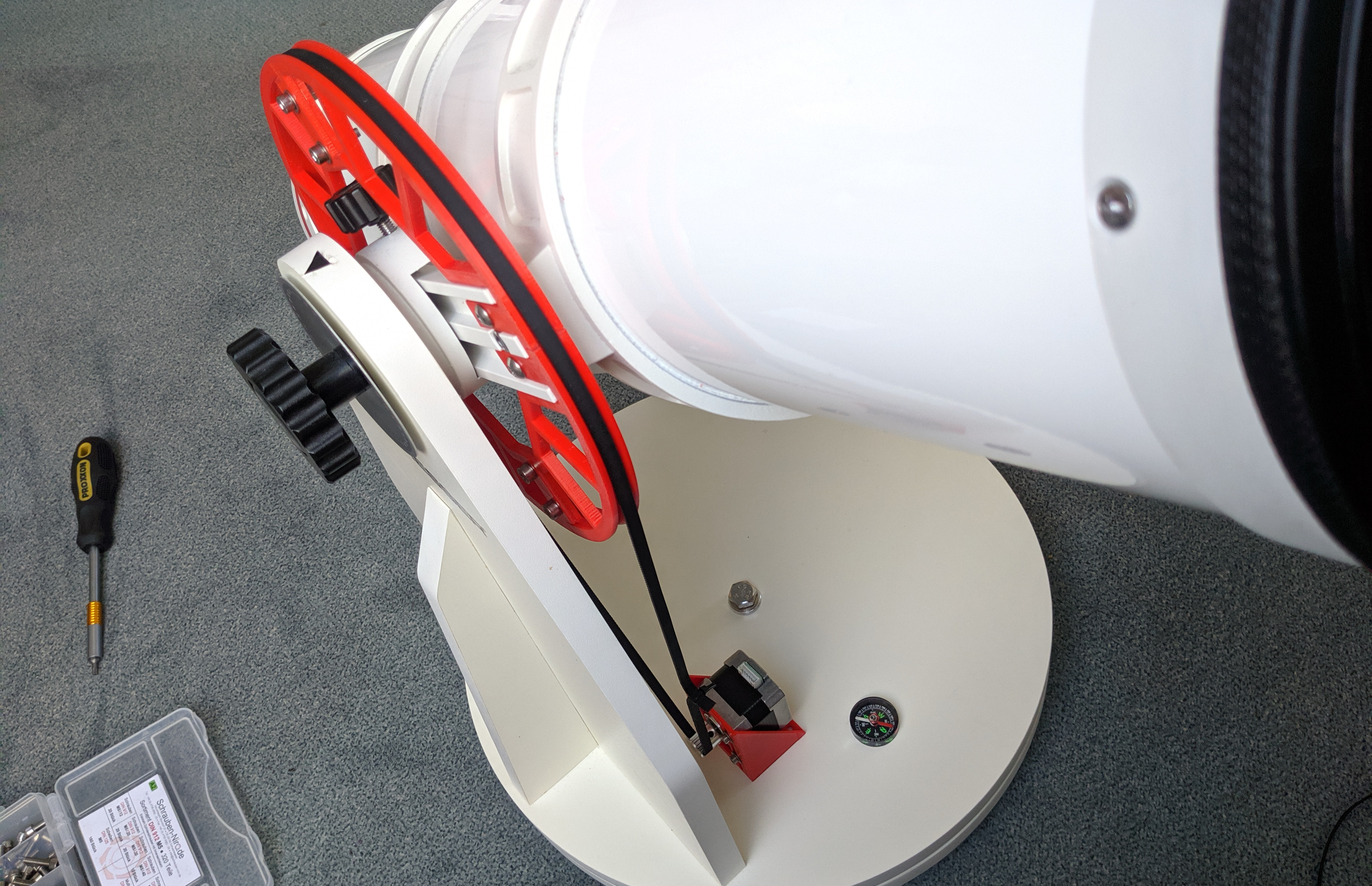
In the end I put the tubus back on the original wooden base:
 Then cut of a piece of belt and connected the end with a cable tie (just like on 3d printers).
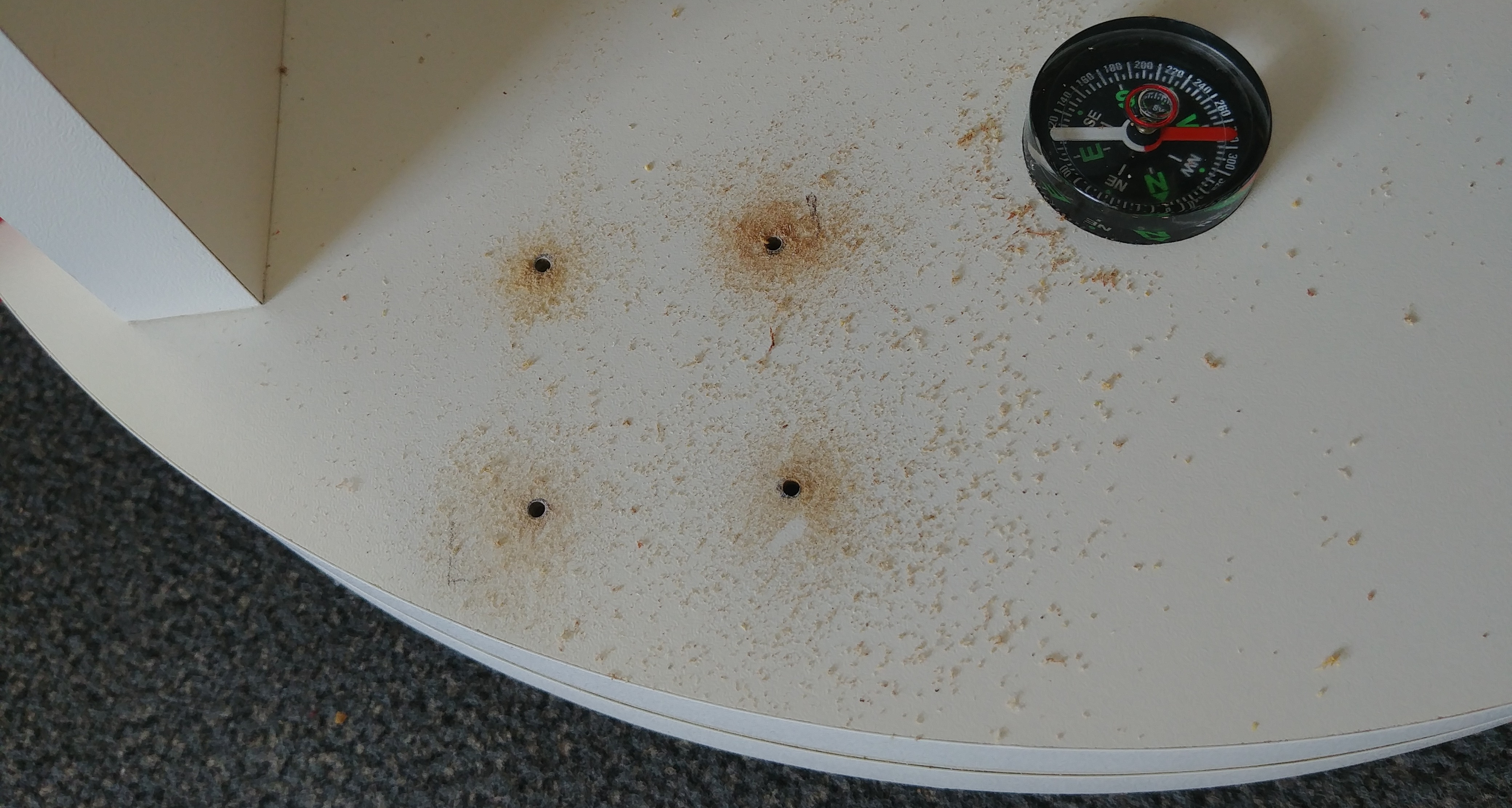
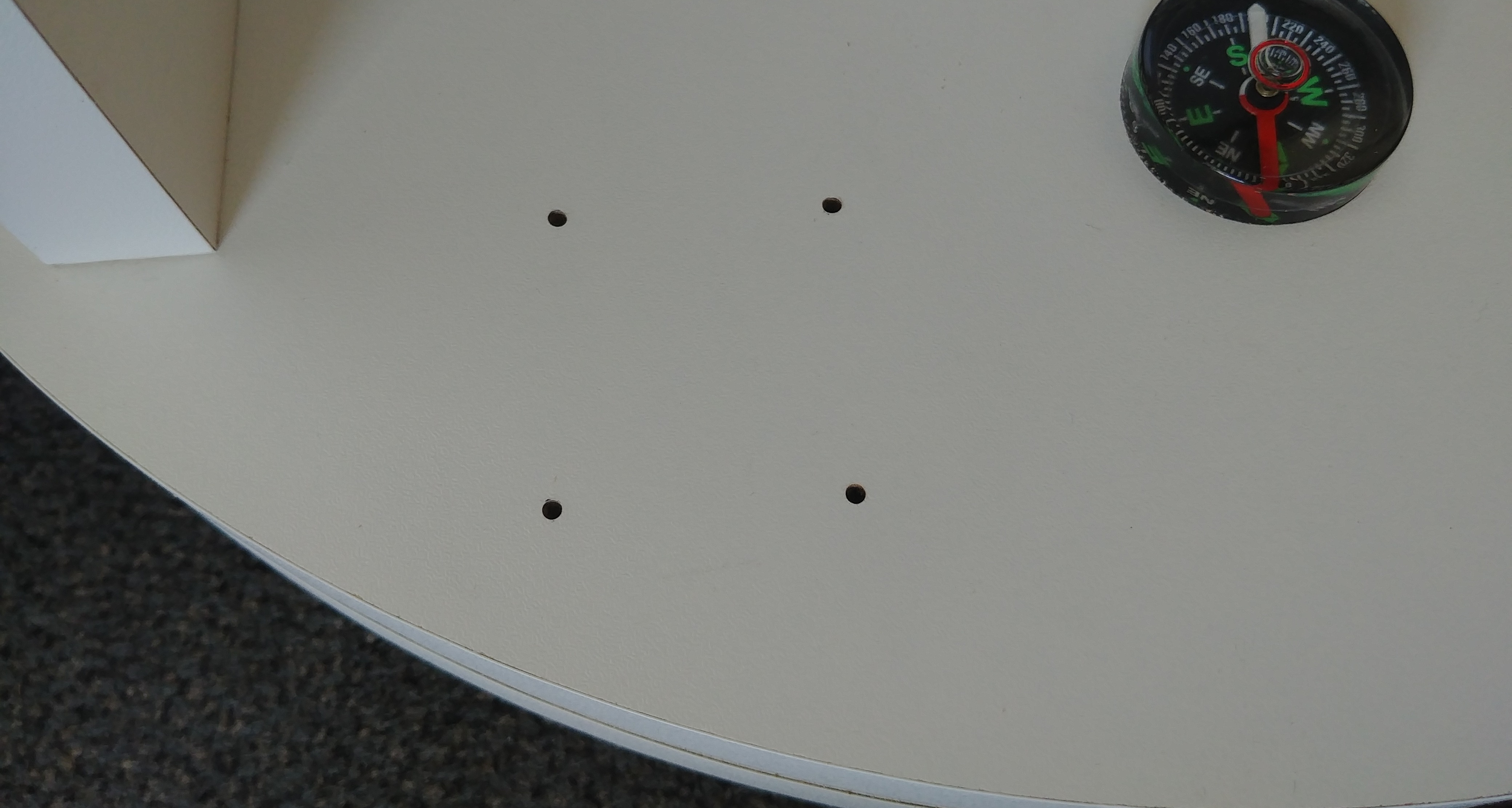
I pre drilled four holes with a 2 mm drill (3.5 mm screws) for the motor mount:
And secured it with wood screws. Now it is possible to put tension on the belt:
Download
As already mentioned I used the online CAD tool Onshape, so if you want to print it yourself you can download it here (see the tabs on the bottom for all other parts).
They support export as STL and many other CAD formats. It should be also possible to copy the project there (needs an account) and adjust all the variables, like diameter, belt size, sections, tolerance… or make other modifications.
Learnings
After all I want to shortly write about things that I learned and will do differently in the future projects.
Model everything in CAD first
It would have saved a lot of time and also some material, if I would have taken the time to model the whole telescope (including this mounting rail) in CAD first and then assembled it virtually. Without a full model I overlooked some pieces that would collide and had to edit the pulley geometry again.
Support tolerances
The Z axis height for parts on the print bed is very accurate and usually doesn’t need any tolerance. But on supports some tolerance is absolutely required (at least with PrusaSlicer support), 0.5 mm would have been suitable in this case.
Avoid thin and sharp edges
Under normal circumstances this 3D printer does not cause noticeable corner bulging. But with very fine and sharp edges it is a problem. This could have been prevented already in the design, with placing a “valley” on the profile edge, instead of a (half) tooth.