UT61E Toolkit: Update 1.4 with Temperature Measurement
This is another app release that adds new data conversion features. This time: temperature measurement!
I got the idea after watching Dave’s EEVBlog about the new UT61E+, he criticized the unnecessary hFE mode and missing temperature option. He also said that this would be probably just a software change. So I thought: True! This should be even possible with the older UT61E and so I have implemented it in my app.
Sensor Types
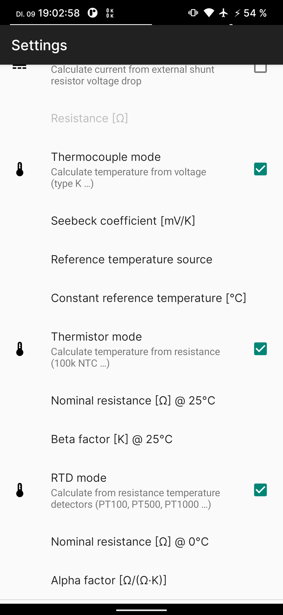
From my research I found 3 general measurement principles and popular sensor types. Each of them has different advantages (more on what to choose later) and needs different parameters. They are now configurable in the settings “data processing” category:
All of them include some standard values, that should fit the typical sensors already.
Note that multiple options can be enabled at the same time. The app then uses the first in the list that fits to the selected range and just applies that calculation. For example if everything is enabled, but the multimeter returns mV values it automatically uses the thermocouple conversion, because it is the only that produces a voltage. Thermistor and RTD are both measured as resistors, so you have to disable thermistors if you want to connect a RTD instead.
The next sections give a quick introduction how the supported sensor types work.
Thermocouple
A very popular sensor, this is usually the only option on meters that already include temperature measurement.
The sensor consists of 2 wires from different metals. They are connected at on end in the measurement junction and on the other side usually to copper and connected to a voltmeter. The connection to copper forms a reference junction, also called cold junction, but it does not need to be actually colder than the measurement junction. A voltage is generated depending on the temperature difference between the junctions, it is practically linear. Polarity can change, depending on which junction is hotter/colder.
Multimeter banana jacks are typically placed 19 mm apart, so probes made for other devices fit nicely without modification:
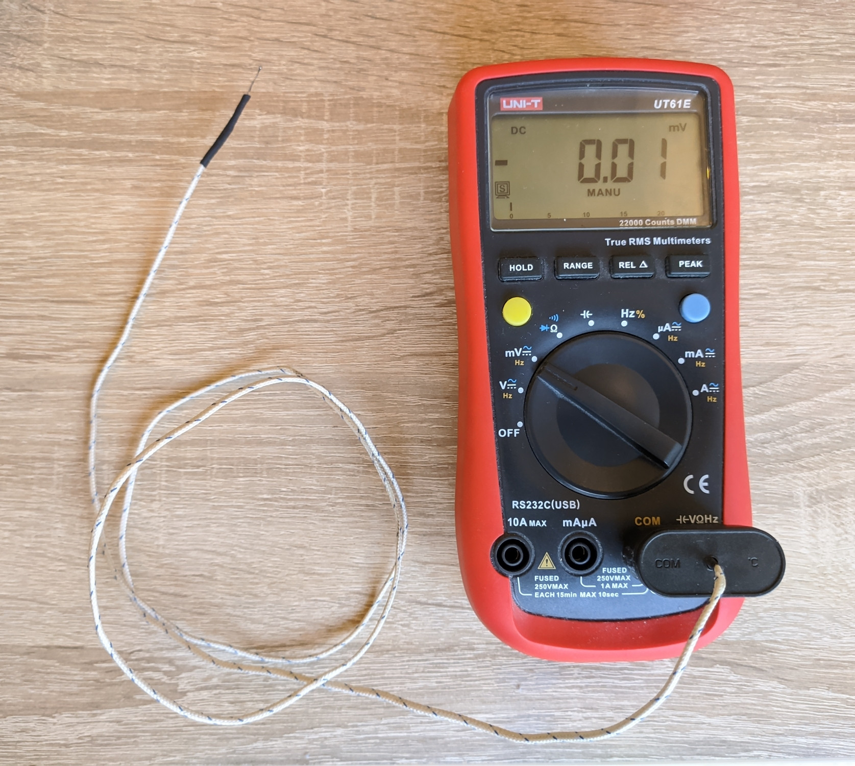
Note: Voltage is almost 0 here, because both junctions are at ambient temperature.
To calculate the temperature we need to know how much the voltage increases per degree C. Preset is 0.039 mV/K (I am using Kelvin for temperature differences here, but it is of course 1:1 with °C). This is the value for a standardized type K sensor.
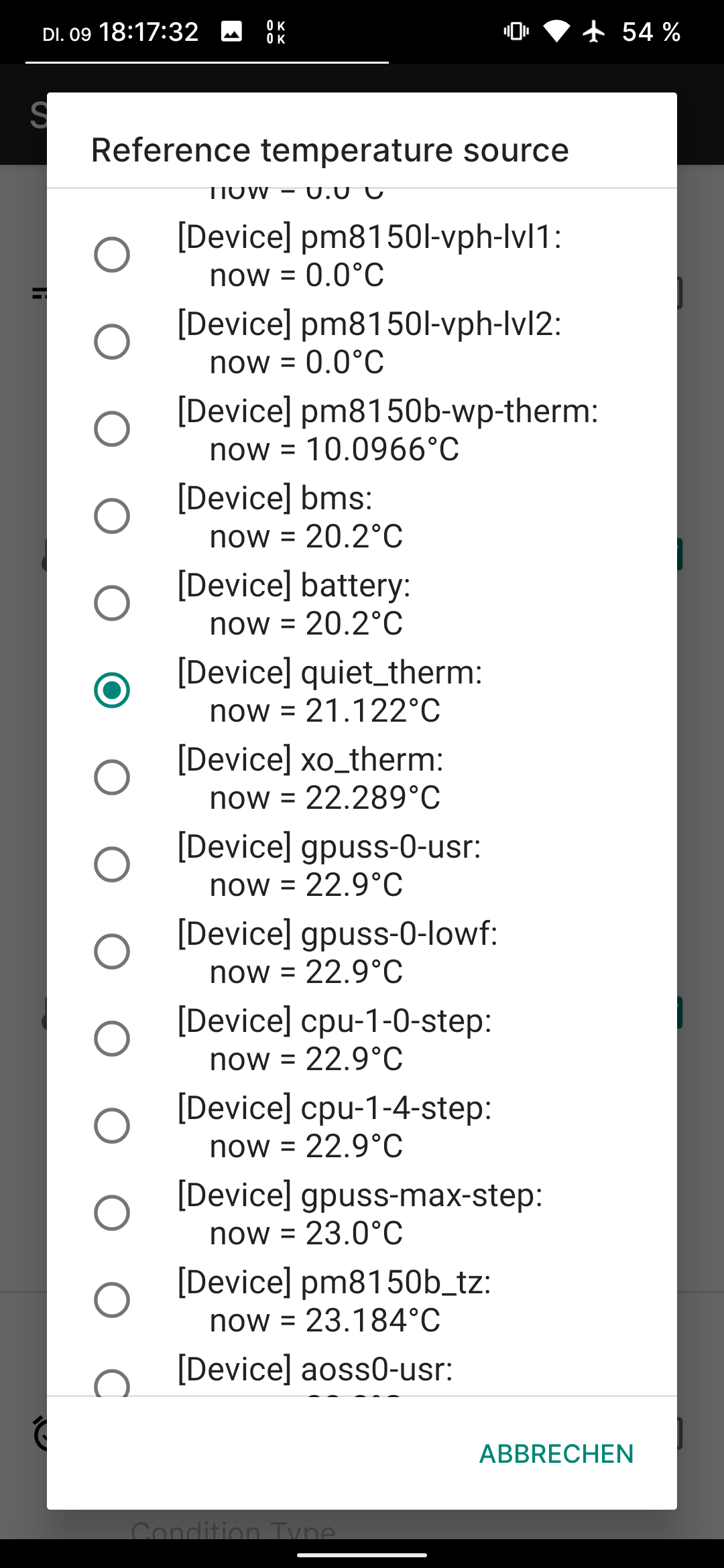
In addition we need the temperature of the reference junction. There are multiple options, as you can see in the following app screenshots:
If you have a stable ambient temperature you can select “constant” and manually put in a temperature (default = 20 °C), this is the most reliable option.
Otherwise it is possible to use sensors from the connected smartphone for this. Most devices include temperature sensors for CPU/GPU, battery, etc… in my case 81 sensors! Not all report a valid measurement though, some are deep in the negative or always 0.0. Select one that looks valid, here battery related ones are pretty good. Obvious potential issue is the self heating of the smartphone, it will probably report a bit more than ambient. But the advantage is that it continuously updates, it should not be distorted too much if you don’t touch or otherwise use the phone while measuring.
The multimeter should be in the 220 mV range and provide 0.01 mV resolution, combined with
0.039 mV/K this gives a resolution of about 1/4 = 0.25 K.
Other ranges are not necessary as 220 mV / 0.039 = ± 5600 K is much more then these sensors can withstand anyway.
Thermistor
The name is a combination of thermal and resistor, this already explains what it is: a simple resistor. Typically NTCs (negative temperature coefficient) are used as sensors, so the resistance gets lower if the temperature increases.
Calculation of the temperature from the resistance is non-linear, which makes it more complex. For example a bit of python code to get the resistance from temperature:
r0 = 100_000 # Ohm
t0 = 25 + 273.15 # absolute temperature for r0
beta = 3950 # change rate coefficient

def resistance(c):
    k = c + 273.15
    return r0 * exp(beta * (1/k - 1/t0))
It contains the exponential exp() function (based on e = 2.71828...) and this causes massive changes in resistance, which makes it a challenge to measure over large temperature ranges. For example a NTC with 100 kΩ @ 25°C has 200 kΩ @ 10°C (with 10 kΩ/K change rate) and 3.59 kΩ @ 125°C (with 0.09 kΩ/K change rate).
Read more: https://reprap.org/wiki/Thermistor
https://github.com/reprap/firmware/blob/master/createTemperatureLookup.py
With the usual fixed voltage dividers this reduces the resolution, but with the UT61E it is quite a bit different, I made a graph to make this better visible:

The blue line shows the thermistor resistance from -100 °C up to 250°C , it is logarithmically scaled on the right Y axis, otherwise it would be impossible to see. On the low end it goes over 1e9 Ω = 1 GΩ while at the high temperatures it is just a few hundred Ohms. Nominal resistance is again 1e5 Ω = 100 kΩ.
Then the green line is the max. value of the range the multimeter will be in, this must be always at least as much as the actual resistance, to be able to measure it. Note that below -85 °C this does not work anymore, because it can’t measure > 220 MΩ.
Now the red line shows the resolution, as you can see the autoranging is really helpful here. The resolution is naturally getting worse with increasing temperature, but switching to a lower resistance range counteracts this. Worst case is 0.02 K and best case < 0.001 K, which is extremely fine.
At 20 °C is also a good area with about 0.002 K, in my tests this even detects the heat radiation from my body, could be made into some sort of distance sensor.
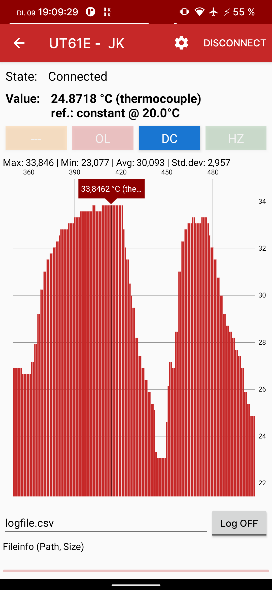
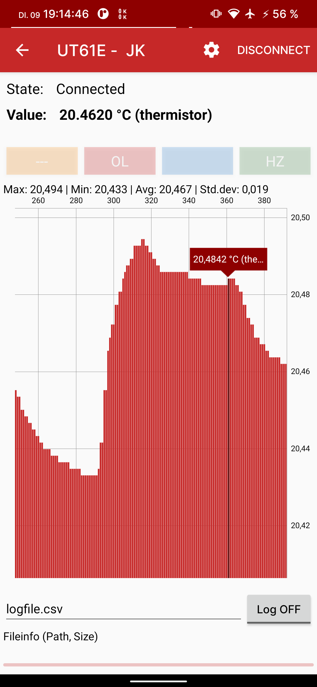
Here is how it looks in the app, again showing the resolution:
Resistance Temperature Detector (RTD)
RTDs are also resistors, but with a positive temperature coefficient and made out of wire or thin film of a pure metal. This makes them practically linear and gives them good accuracy and repeatability (low drift). Typical material is platinum with the PT100, PT500 and PT1000. The number specifies the nominal resistance at 0 °C, this should be configured in the app settings.
Otherwise there is a the alpha, similar to the thermocouple this just specifies how much the resistance changes per degree. The default of 0.00385 Ω/(Ω·°C) is standardized and should fit almost anything.
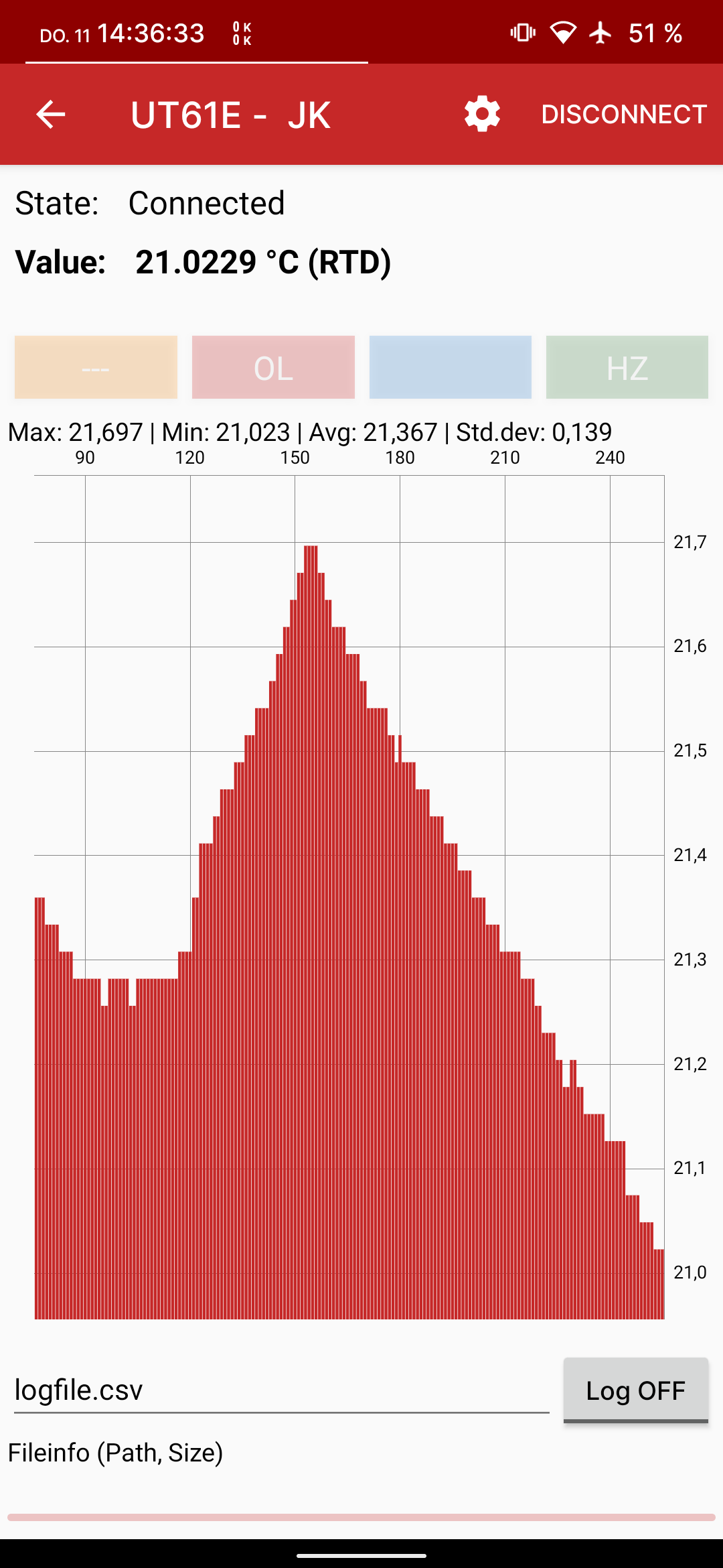
It looks like this in the app:
Resolution on the UT61E with PT100 and PT1000 is equal:
0.00385 * 100 Ω = 0.385 Ω/K in 220 Ω range with 0.01 resolution = 1/38 = 0.026 K
0.00385 * 1000 Ω = 3.85 Ω/K in 2.2 kΩ range with 0.1 resolution = 1/38 = 0.026 K
It will just switch to the better matching range. Other ranges are not required up to (220-100) Ω / 0.385 = +312 °C after that it will switch up (factor 10) and reduce the resolution to 0.26 K.
Sensor Selection
After all you might ask: What sensor should I choose? For that I have made an short overview:
| Type | Sensor | Max. T | Resolution | Accuracy | Cost incl. wire |
|---|---|---|---|---|---|
| Thermocouple | Type K | 1200 °C | 0.25 K | 2 K (0.75%) | ~ 1 $ |
| Thermistor | NTC 100k | 300 °C | 0.001-0.02 K | 3-15 K (5%) | ~ 0.5 $ |
| RTD | PT1000 | 600 °C | 0.026 K | < 0.5 K | ~ 3 $ |
Thermocouples are good for very high temperatures, but resolution and accuracy is not the best. Thermistors on the other hand provide insanely high resolutions, but only at relatively low temperatures and the accuracy is pretty bad, because of the non linearity. RTDs are the most accurate (and expensive), with acceptable resolution and max. temperature.
As always: there is no clear winner, it really depends on the application.