I2C Communication Protocol of a Smartphone Battery
In this post I investigate how a typical Oneplus smartphone battery communicates the current voltage, state of charge etc. to the main device. This can be also useful for repurposing these batteries on a Raspberry or Orange Pi, to power portable projects.
Hardware Dismantling
I had the battery already removed from the Oneplus One (and replaced with a new third party part).
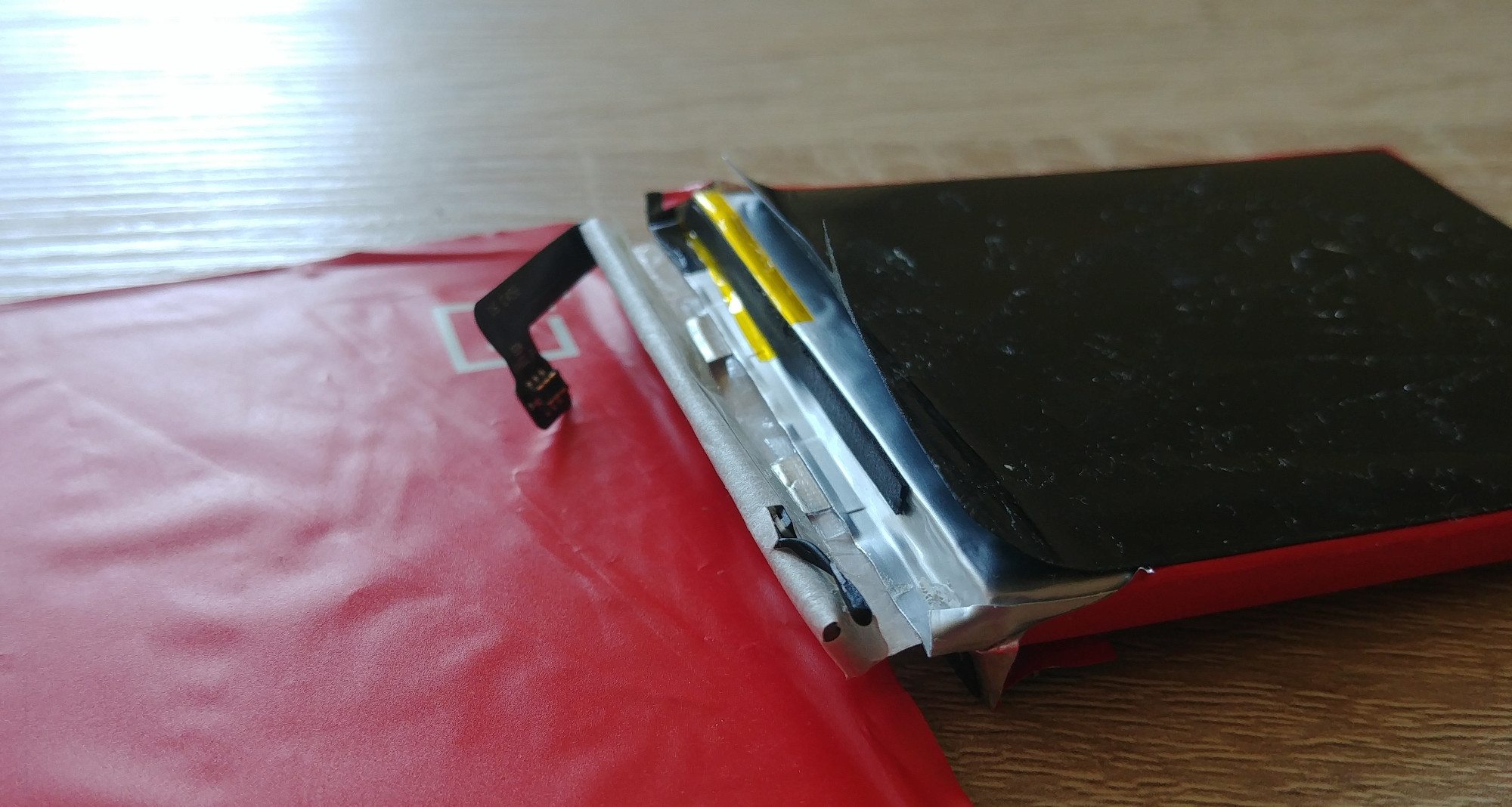
First the outer wrap has to be removed, I need to see the bare cell and protection PCB. It reveals another (paper?) wrap at the top and a small temperature probe sticking out:
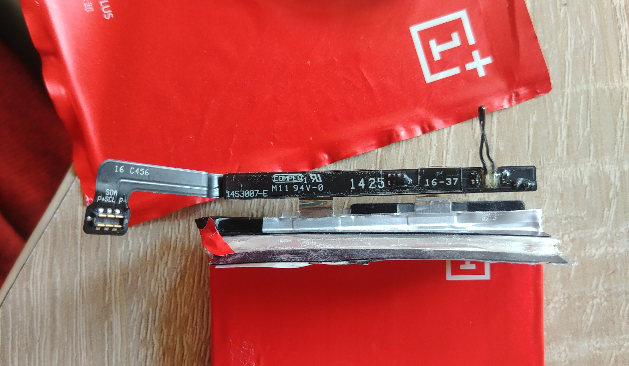
After removing that as well the board is finally visible. Between the big battery taps is most likely a shunt resistor to measure the current. On the mid to left are some ICs (more on them later) and on the right four large solder pads, marked with SCL, SDA, P+ and P-. The flat flex cable is simply soldered to these pads and the connector has the same markings.
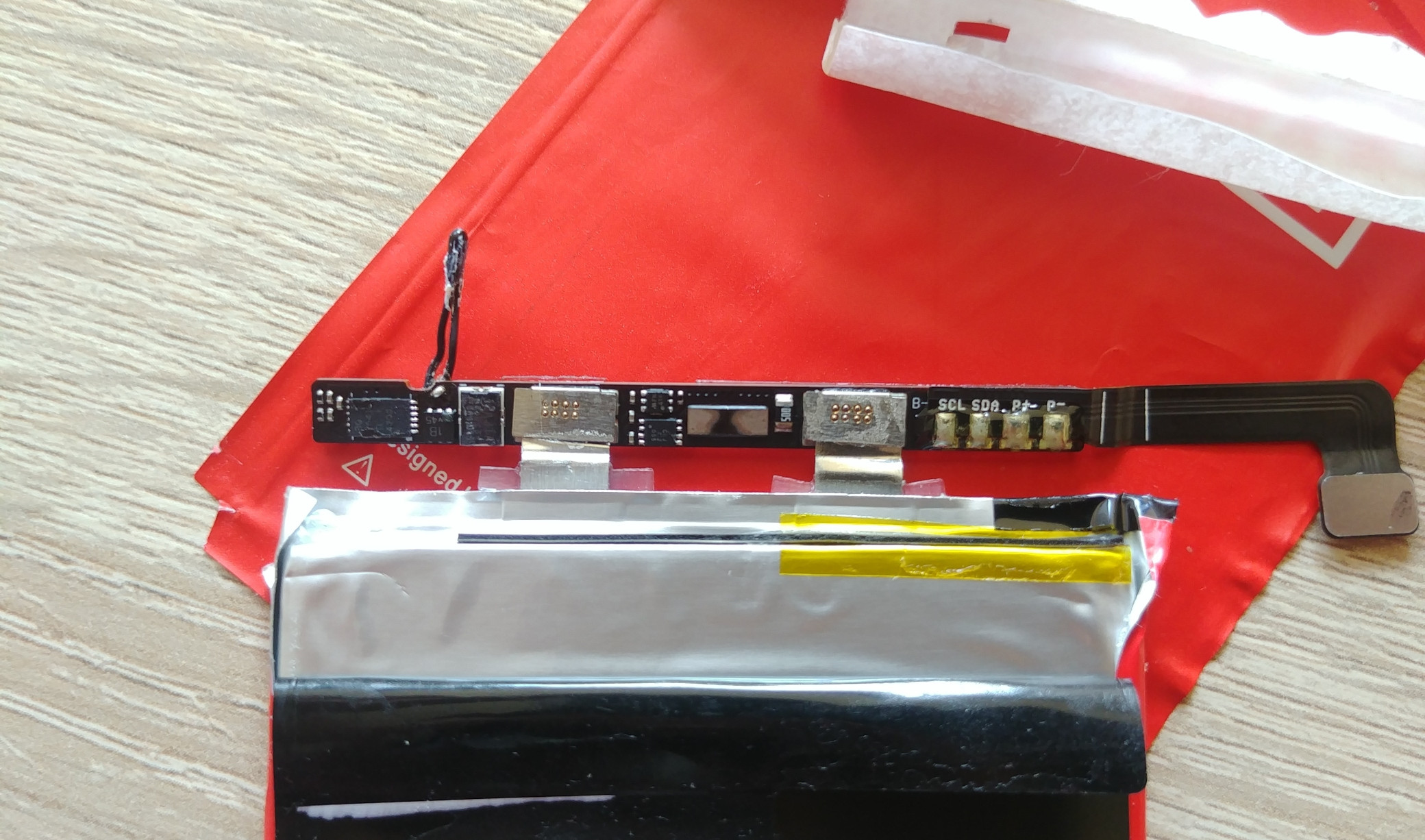 P stands probably for power and these +/- pads are indeed connected to the battery and carry the about 4V, I have checked it with a multimeter.
SCL/SDA is really interesting, because this suggests that there is some digital I2C communication with the smartphone going on.
P stands probably for power and these +/- pads are indeed connected to the battery and carry the about 4V, I have checked it with a multimeter.
SCL/SDA is really interesting, because this suggests that there is some digital I2C communication with the smartphone going on.
 Not much on the back side, looks like a few SMD resistors are below some black potting compound.
Chip Investigation
Now I got curious what exactly this board does. Unfortunately I could not read chip markings, because they are extremely small, no chance without a microscope…
Instead I tried to find something on the internet, the search for “oneplus battery i2c site:forums.oneplus.com” brought up a boot/kernel log. Then searching for “battery” in the log found these messages:
[    4.792738] bq27541-battery 1-0055: DEVICE_TYPE is 0x541, FIRMWARE_VERSION is 0x200
[    4.792950] bq27541-battery 1-0055: Complete bq27541 configuration 0x601B
This is a kernel driver for “bq27541”, so I searched for that and got indeed a datasheet from Texas Instruments. The description fits well, it is a “Single Cell Li-Ion Battery Fuel Gauge” and “provides information such as remaining battery capacity(mAh), state-of-charge (%), run-time to empty (min.), battery voltage (mV), and temperature (°C)” over an I2C interface.
The protocol description is detailed, important information for the start is on page 32:
- device address 01010101 = 0x55
- support for normal I2C read or incremental read (multi byte)
Abd a excerpt from the standard 2 byte registers/commands (page 9):
- TEMP (temperature)
0x06+0x07 - VOLT (voltage)
0x08+0x09 - SOC (state of charge)
0x2c+0x2d
To confirm that it speaks this protocol I hooked up my DSLogic Plus, connected the battery back to the phone and rebooted it, the capture looks like this:
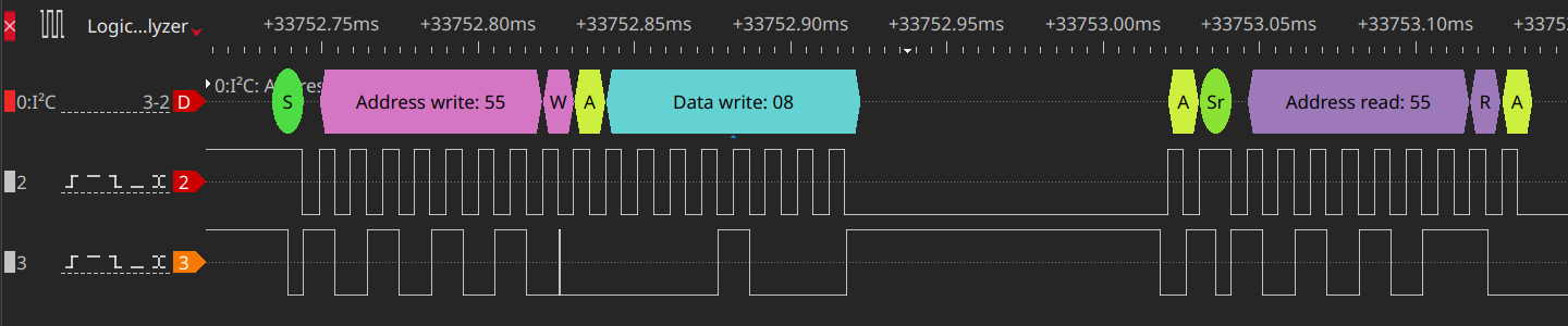 The 7 bit long address is
 0x55 as expected, after that comes 1 bit indicating a read/write, then ACK (A) or NOT ACK (N) and finally the packet data. It is the register 0x08 = voltage in this case. The request is always a write, but it is not actually writing, just specifies the register.
I2C is a bus designed with a master (here: phone) and slave (here: battery).
The master controls the bus, it sends again the first start with device address, but now with read bit appended. Now the bus gets released from the master, indicating that the slave 0x55 is allowed to send now. It responds shortly after with the actual data:
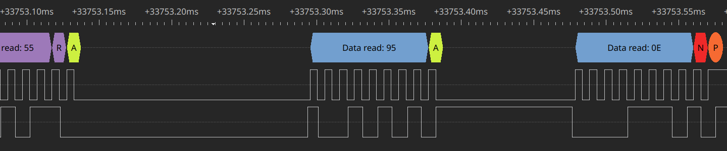 First comes the low byte, high byte is second (practically little endian), that means
 0x0e95 = 3733 mV.
Orange Pi Setup
As already noted in the introduction this is also useful for usage with other Linux computers. I had a Orange Pi PC2 with Armbian laying around, so I used that, it has many GPIOs:
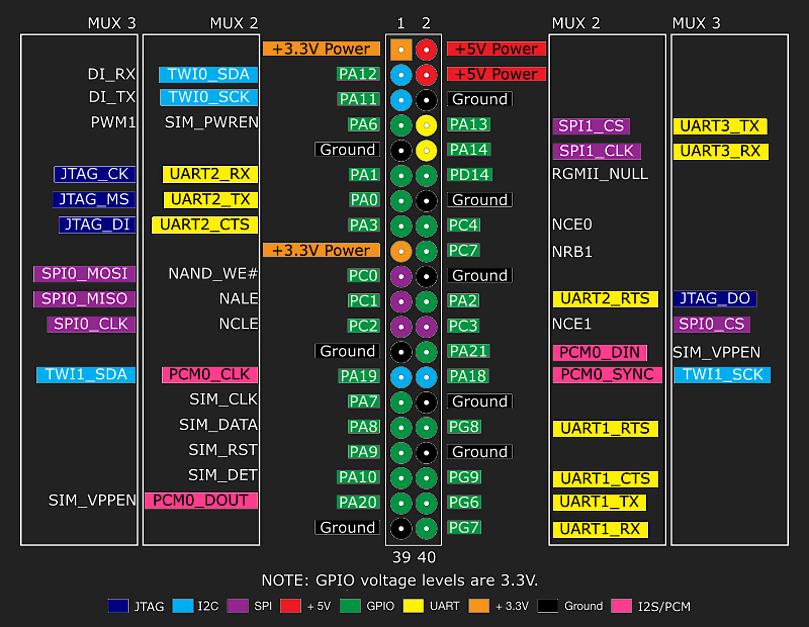 Most importantly, support for I2C. Bus 0 is on PA11 and PA12, highlighted in light blue. On modern kernels the so called device trees (DT) are used to define the hardware. For Armbian the configuration file which gets read by the bootloader is
 /boot/armbianEnv.txt. To enable I2C bus 0 is must contain overlays=i2c0.
After a reboot a new I2C bus should show up, this can be checked with i2cdetect -l.
So I connected both the battery and the logic analyzer to it:
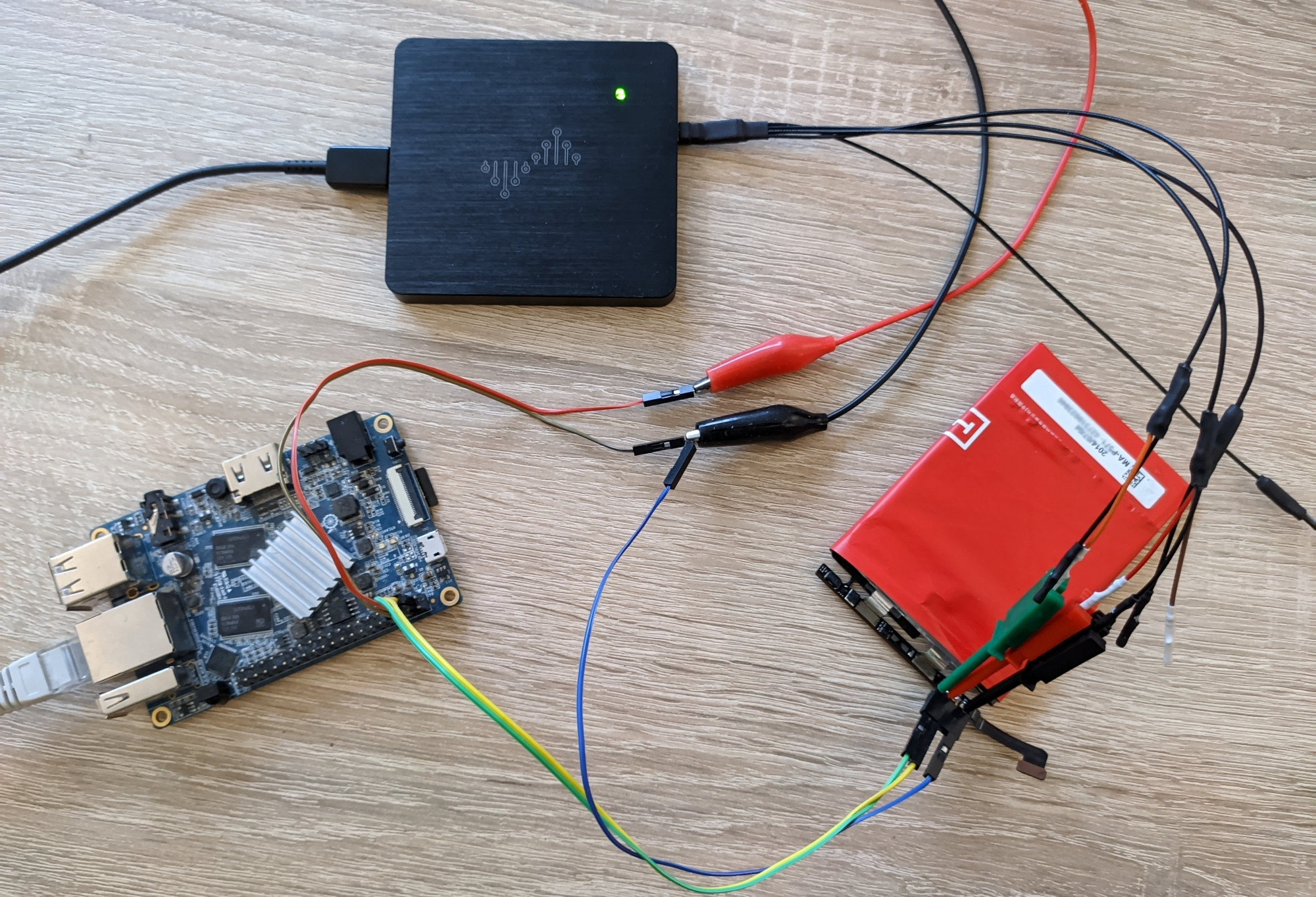 The red and black crocodile clips are coming from a lab power supply, simply providing 5V to power the Orange Pi, battery ground is also connected to the common ground.
It is also possible to scan for devices with i2cdetect, here with -y to disable interactive confirmation and on bus 0:
orangepipc2:~:# i2cdetect -y 0
     0  1  2  3  4  5  6  7  8  9  a  b  c  d  e  f
00:          -- -- -- -- -- -- -- -- -- -- -- -- --
10: -- -- -- -- -- -- -- -- -- -- -- -- -- -- -- --
20: -- -- -- -- -- -- -- -- -- -- -- -- -- -- -- --
30: -- -- -- -- -- -- -- -- -- -- -- -- -- -- -- --
40: -- -- -- -- -- -- -- -- -- -- -- -- -- -- -- --
50: -- -- -- -- -- 55 -- -- -- -- -- -- -- -- -- --
60: -- -- -- -- -- -- -- -- -- -- -- -- -- -- -- --
70: -- -- -- -- -- -- -- --
It indeed detects the battery with address 0x55, very nice!
Command Line Readout
With the included i2cdump and i2cget tools it is possible to read data out from a shell.
The dump reads a range of bytes, here again with -y to disable interactive confirmation, range 0x02-0x2d for the standard registers, bus 0 and address 0x55.
W for 16 bit words, because the chip returns directly 2 bytes, no need to send request for every single address.
orangepipc2:~:# i2cdump -y -r 0x02-0x2d 0 0x55 W
     0  1  2  3  4  5  6  7  8  9  a  b  c  d  e  f    0123456789abcdef
00:       00 00 ff ff 71 0b 66 0f 80 01 13 06 27 09      ....q?f???????
10: 02 05 16 08 00 00 ff ff ff ff ff ff ff ff 8a f8    ????..........??
20: 28 00 46 12 00 00 ff ff 6f 0b c0 03 3e 00          (.F?....o???>.

orangepipc2:~:# i2cget -y 0 0x55 0x08 w
0x0f66

orangepipc2:~:# i2cget -y 0 0x55 0x2c w
0x003e
If you want only a single value then the get is the right tool, after specifying bus and address there is a single register and word to read 2 bytes.
Here I read out voltage 0x0f66 = 3942 mV and 0x3e = 62 % state of charge (soc).
Python Readout
Another good option to get the data programmatically is Python. A popular library exists for SMBus, which is based on the I2C protocol. It provides also the low level methods required here. On my Ubuntu 20.04 based Armbian it can be simply installed through apt:
orangepipc2:~:# apt search smbus
...
python3-smbus/focal 4.1-2build2 arm64
  Python 3 bindings for Linux SMBus access through i2c-dev

orangepipc2:~:# apt install python3-smbus
...
Otherwise pip works as also as usual.
For testing I use a interactive python prompt. SMBus() receives a argument for the bus number, 0 in this case:
orangepipc2:~:# python3
Python 3.8.5 (default, Jan 27 2021, 15:41:15)
[GCC 9.3.0] on linux
Type "help", "copyright", "credits" or "license" for more information.

>>> import smbus
>>> b = smbus.SMBus(0)
>>> b.read_word_data(0x55, 0x8)
3942
>>> b.read_word_data(0x55, 0x2c)
62
>>> b.read_word_data(0x55, 0x6) / 10 - 273.1
19.69999999999999
Again reading words (2 byte) here, in addition to the voltage and soc now also 0x06 = temperature. The result is in 1/10 Kelvin, so it needs the 273.1 offset to get degrees celsius.
Kernel Driver
Okay, enough of the manual playing around. From the the previous look at the Android log it clear that there exists full kernel drivers already. Actually they are in the mainline kernel! This makes installation easier, but just loading the kernel module does not do it. Trust me, I have tried it.
Device Tree Overlays
Like on the basic I2C setup a device tree entry is required, but there is no ready-made overlay included for this driver, so it is necessary to make it yourself. Armbian has documentation and examples that helps to do this.
A more detailed description of the syntax is available at elinux.org (embedded Linux wiki).
Last but not least in the kernel repo is documentation on how to write overlays for the current version. The Armbian sunxi examples are bit outdated, now it is not needed (or recommended) anymore to wrap the definition with fragment@0,__overlay__, etc.
Also I have read the battery node and TI BQ27xxx driver documentation.
It includes a example DT snippet, I adjusted and saved it in i2c-bq27541.dts (.dts = DT source), that is the result:
/dts-v1/;
/plugin/;

&i2c0 {
    #address-cells = <1>;
    #size-cells = <0>;
    bat: battery {
        compatible = "simple-battery";
        voltage-min-design-microvolt = <3200000>;
        energy-full-design-microwatt-hours = <11400000>;
        charge-full-design-microamp-hours = <3100000>;
    };

    bq27541: fuel-gauge@55 {
        compatible = "ti,bq27541";
        reg = <0x55>;
        monitored-battery = <&bat>;
    };
};
Installation was done with armbian-add-overlay, which is just a shell script. It calls dtc (Device Tree Compiler) first and then copies the result to /boot/overlay-user/i2c-bq27541.dtbo (.dtbo = DT binary/blob overlay) and enables it in /boot/armbianEnv.txt. This is pretty convenient, but can be also done manually of course.
Now armbianEnv.txt should contain another line with user_overlays=i2c-bq27541. A reboot is required to actually load it.
Readout
Now if everything worked, the data can be easily read from sysfs power_supply class. I found out that the uevent provides a nice human readable overview:
orangepipc2:jk:# cat /sys/class/power_supply/bq27541-0/uevent
POWER_SUPPLY_NAME=bq27541-0
POWER_SUPPLY_TYPE=Battery
POWER_SUPPLY_STATUS=Charging
POWER_SUPPLY_PRESENT=1
POWER_SUPPLY_VOLTAGE_NOW=3942000
POWER_SUPPLY_CURRENT_NOW=0
POWER_SUPPLY_CAPACITY=63
POWER_SUPPLY_CAPACITY_LEVEL=Normal
POWER_SUPPLY_TEMP=188
POWER_SUPPLY_TECHNOLOGY=Li-ion
POWER_SUPPLY_CHARGE_FULL=2058000
POWER_SUPPLY_CHARGE_NOW=1553000
POWER_SUPPLY_CHARGE_FULL_DESIGN=3000000
POWER_SUPPLY_CYCLE_COUNT=960
POWER_SUPPLY_POWER_AVG=0
POWER_SUPPLY_HEALTH=Good
POWER_SUPPLY_MANUFACTURER=Texas Instruments
Especially interesting is the cycle count of 960 and degraded capacity to just 2058 mAh from over 3000 mAh of a new battery, that info was not accessible through standard Android APIs.
Of course it is also possible to get single values through the other files in this directory, for example just voltage:
orangepipc2:jk:# cat /sys/class/power_supply/bq27541-0/voltage_now
3942000
Note that this is in μV, usually the standard units are the smallest common denominator so there is enough resolution for all drivers and applications.
Further Ideas
It could be used with a lithium battery step up module to power the Orange Pi (or other SBCs with Linux). There are many choices for a few bucks from China that provide 5V output from the single cell input. I have also seen adjustable output (4.3 - 27V) versions, these even include USB charging. Maybe add a display to build a clunky hackable smartphone?