Happybrush Sonic Toothbrush Analysis and Repair
Recently my electric toothbrush stopped working, it showed always the red battery empty indicator, even after leaving it charging overnight. This post shows how it can be opened and possibly fixed. For example a battery replacement is done in the same way.
Disassembly
Preparing for dissasembly the brush head should be removed. Then gently pry up the bottom cover. It has a teeth on both sides, so pushing a flat tool in helps. There is a rubber seal deeper in, try staying above this with sharp tools.
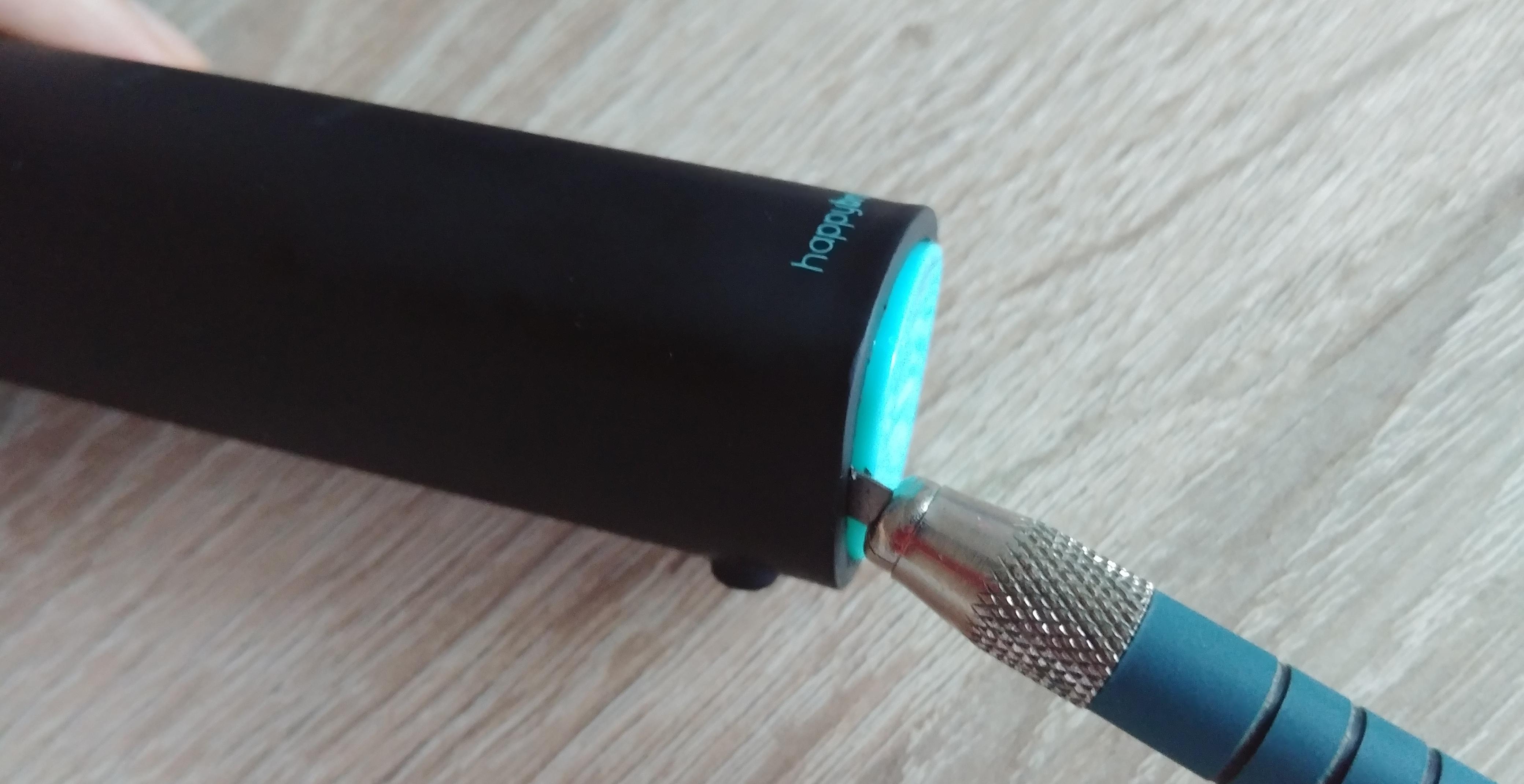
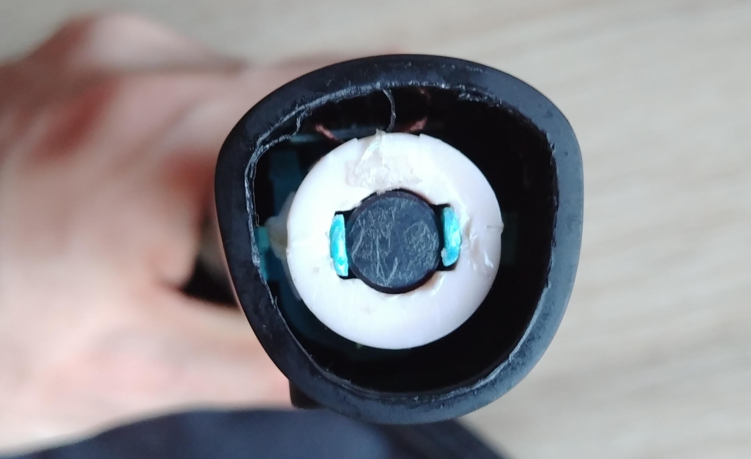
After the case is opened you see the coil for the inductive charging. The ferite core is under as small foam piece in the middle, it also pushes the two clips over the coil, so it must be removed. It might be possible to pull it out with a strong magnet, but this did not work for me, so i had to cut of the clips:
 Then the coil can be pulled out, which frees two other plastic noses below.
Pushing from the top and simultaneously helping with a flat screwdriver to hold the clips on the bottom away from the outer case
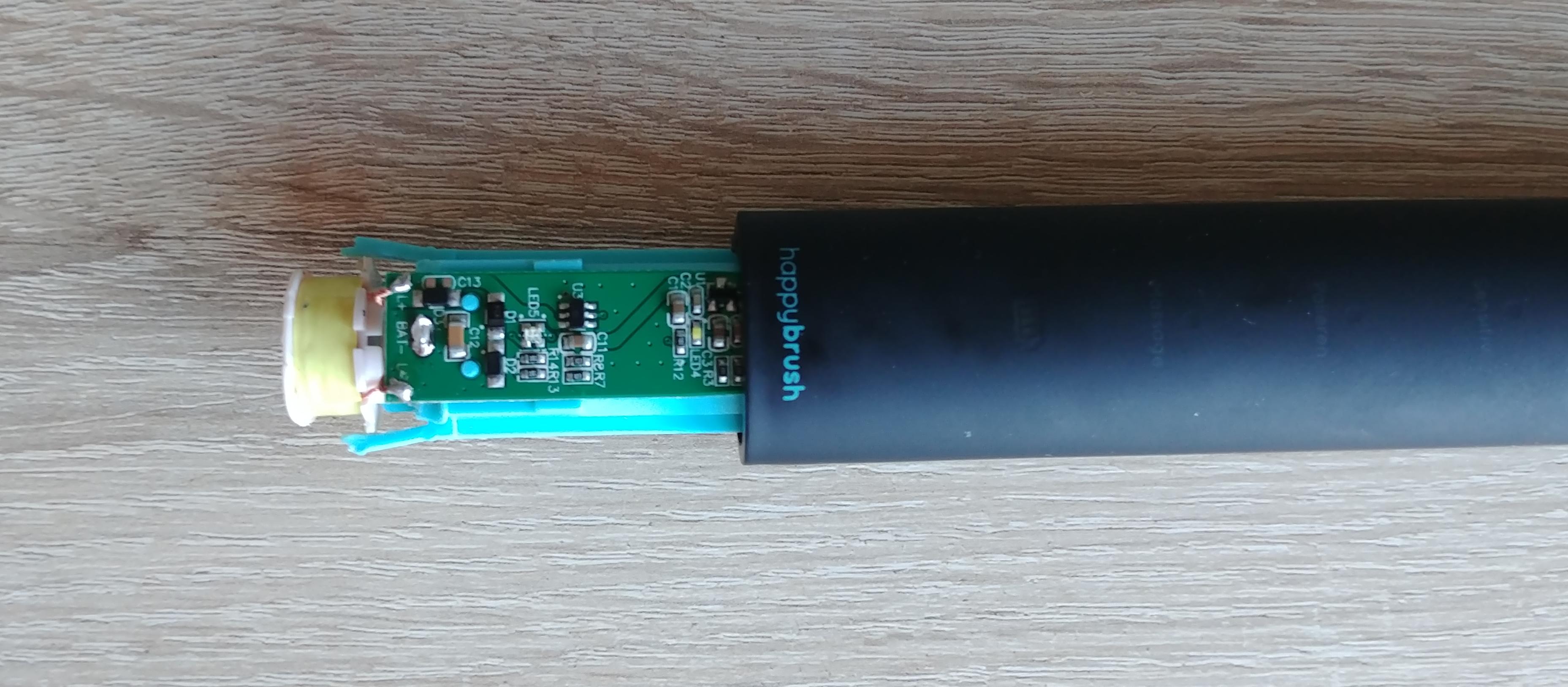
reveals the whole assembly:
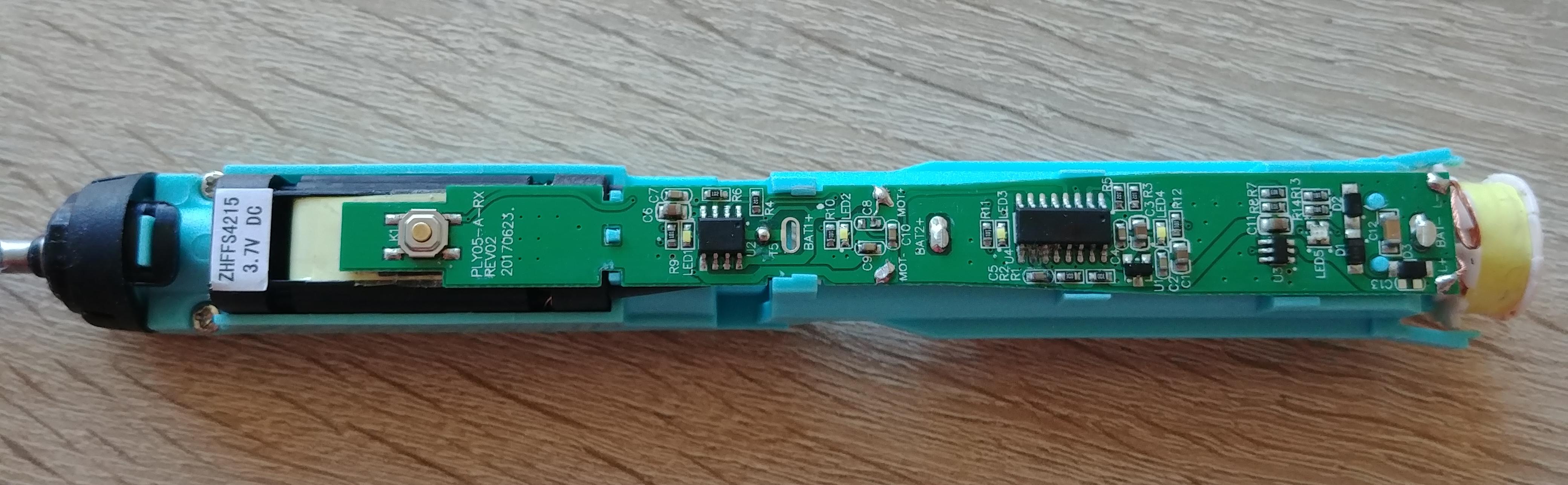 The ZHFFS4215 motor data is availible on the manufacturer website, it apperently draws 0.3 A with no load, 0.6 A at max. efficency and delivers 2.3W. In theory this should allow it to run from 80 - 160 minutes on the builtin 800 mAh cell.
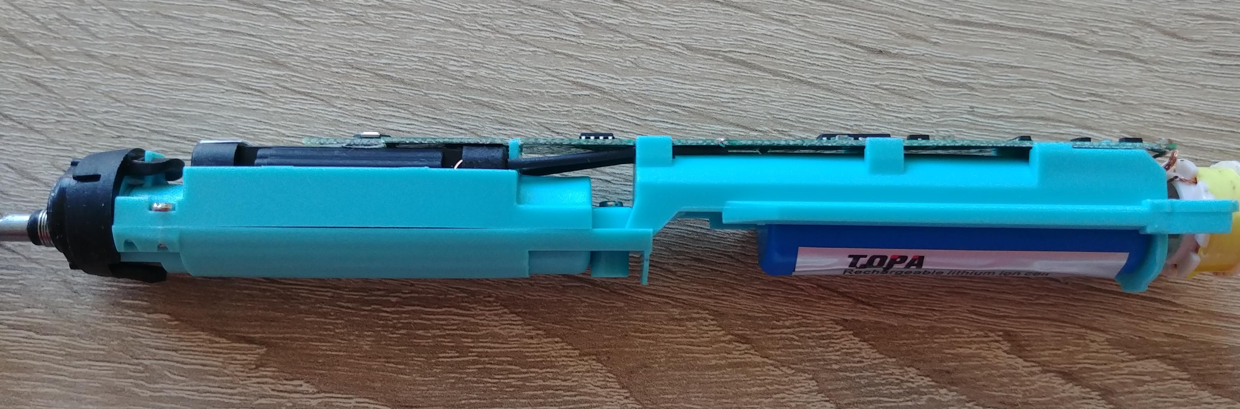
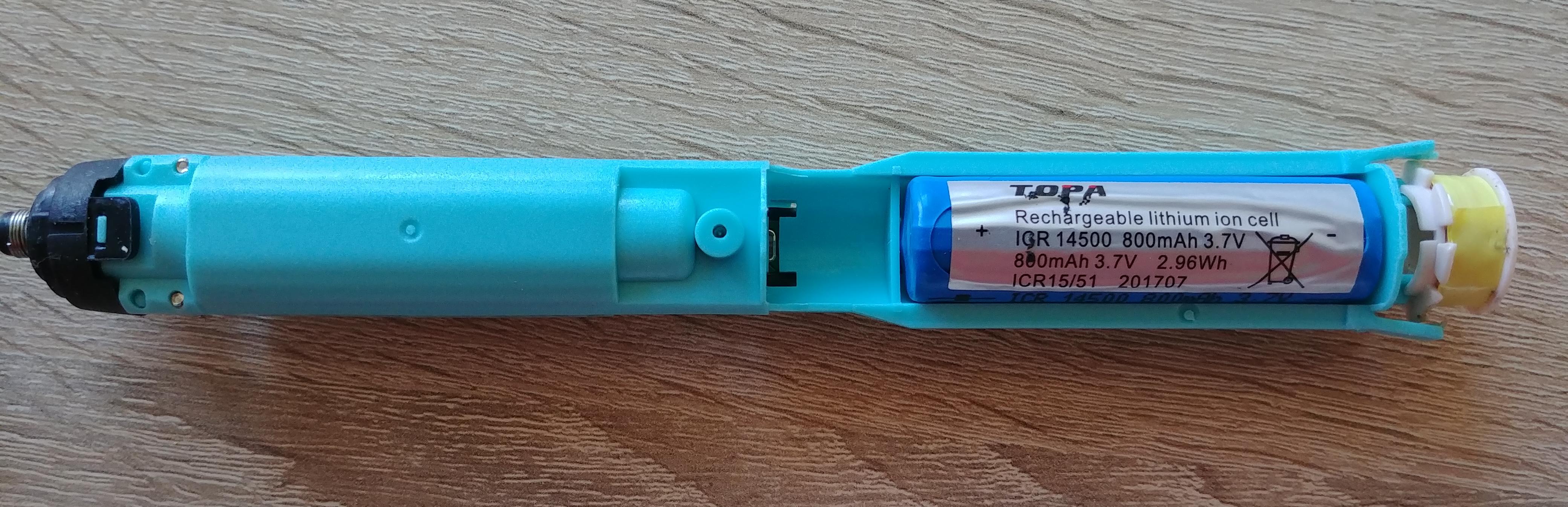 Interestingly there is quite a bit of space unused. The length of the Li-ion cell is only 50 mm, but the holder could take up to 65 mm, there is even a second soldering point for larger cells. A possible mod could be a 14650 cell, with up to 1200 mAh. Even a 18650 might be possible, this would require cutting up the holder the sides though.
But let’s fix it first ;)
Repair
First i supected a faulty charing circuit or battery, so i measured this. But it came out fully charged (4.16 V).
After looking over the PCB the problem was obvious, pretty strong corrosion happening on the main control chip:
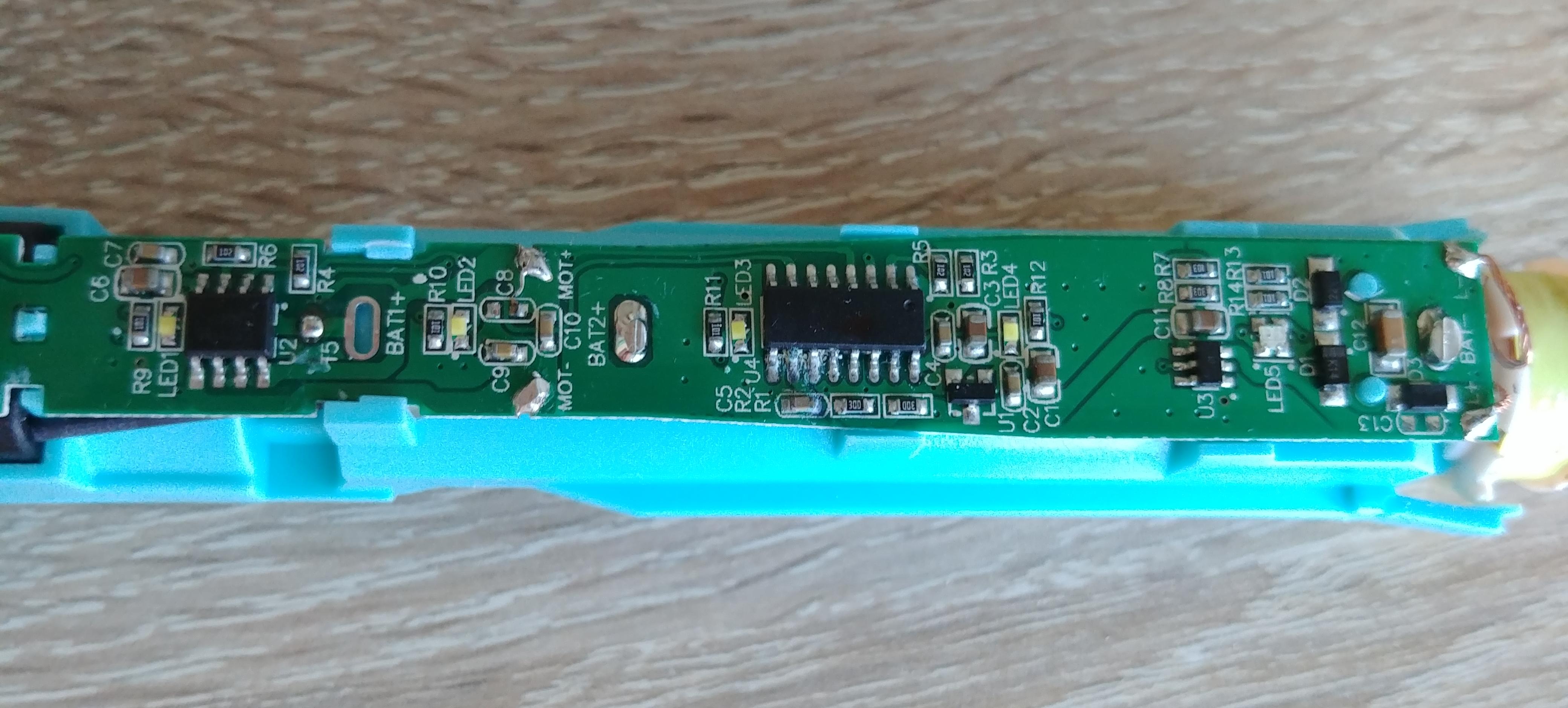 Most likely caused by water tripping into the power button from above. After cleaning it up a bit and refreshing the solder joint it turned on again!
To make it complete, here a shot from the PCB backside, only containing test pads:
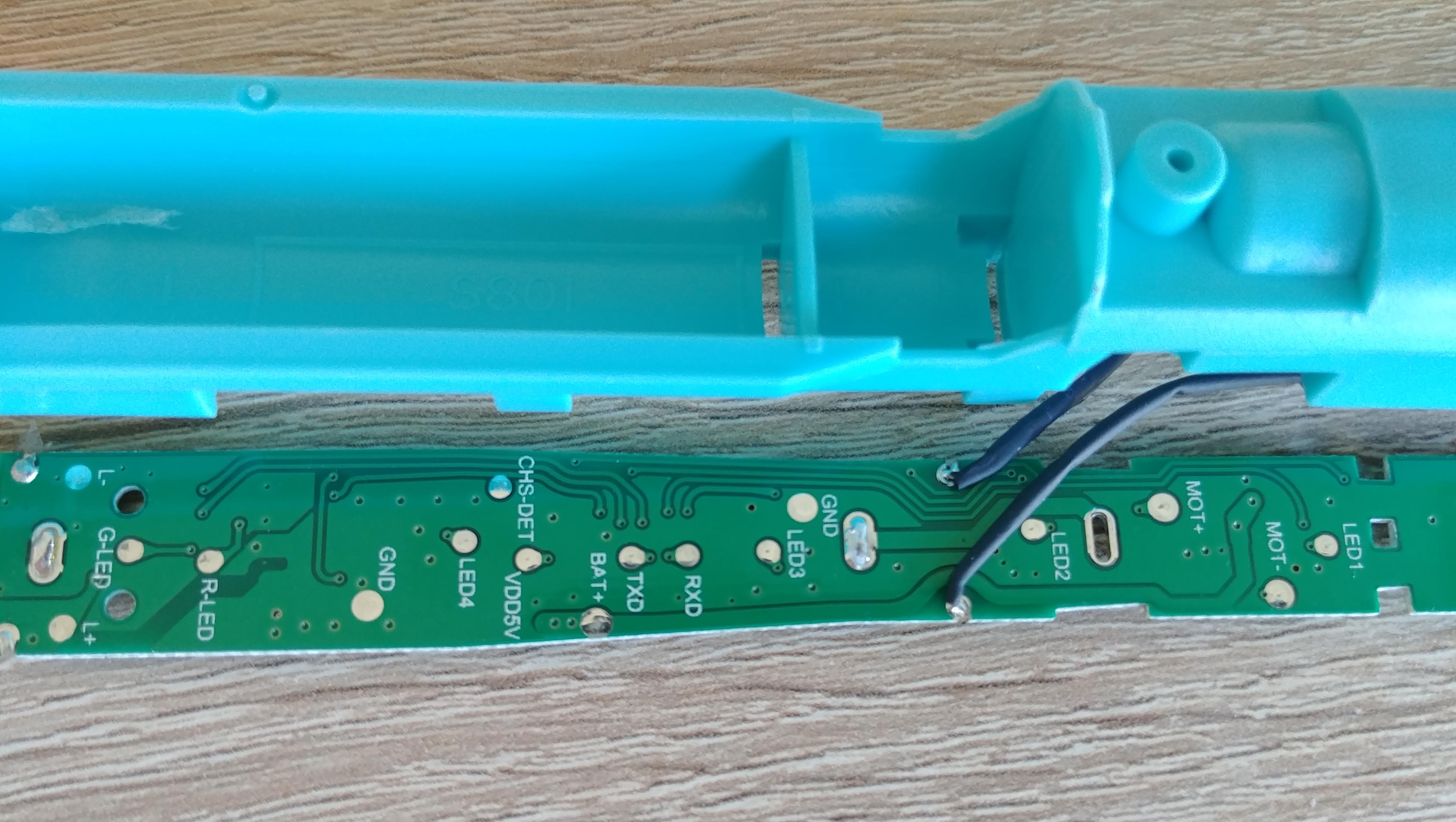 The RXD/TXD pads look interesting, but i did not see any data transmitted here. Could be just for firmware flashing. Unfortunately the chip is completly blank, so it is really almost impossible to identify and figure out how to interact with it.
Frequency measurements
The brush has different cleaning modes, so i was curious how they are implemnted and hooked up an oscilloscope to the motor pins:
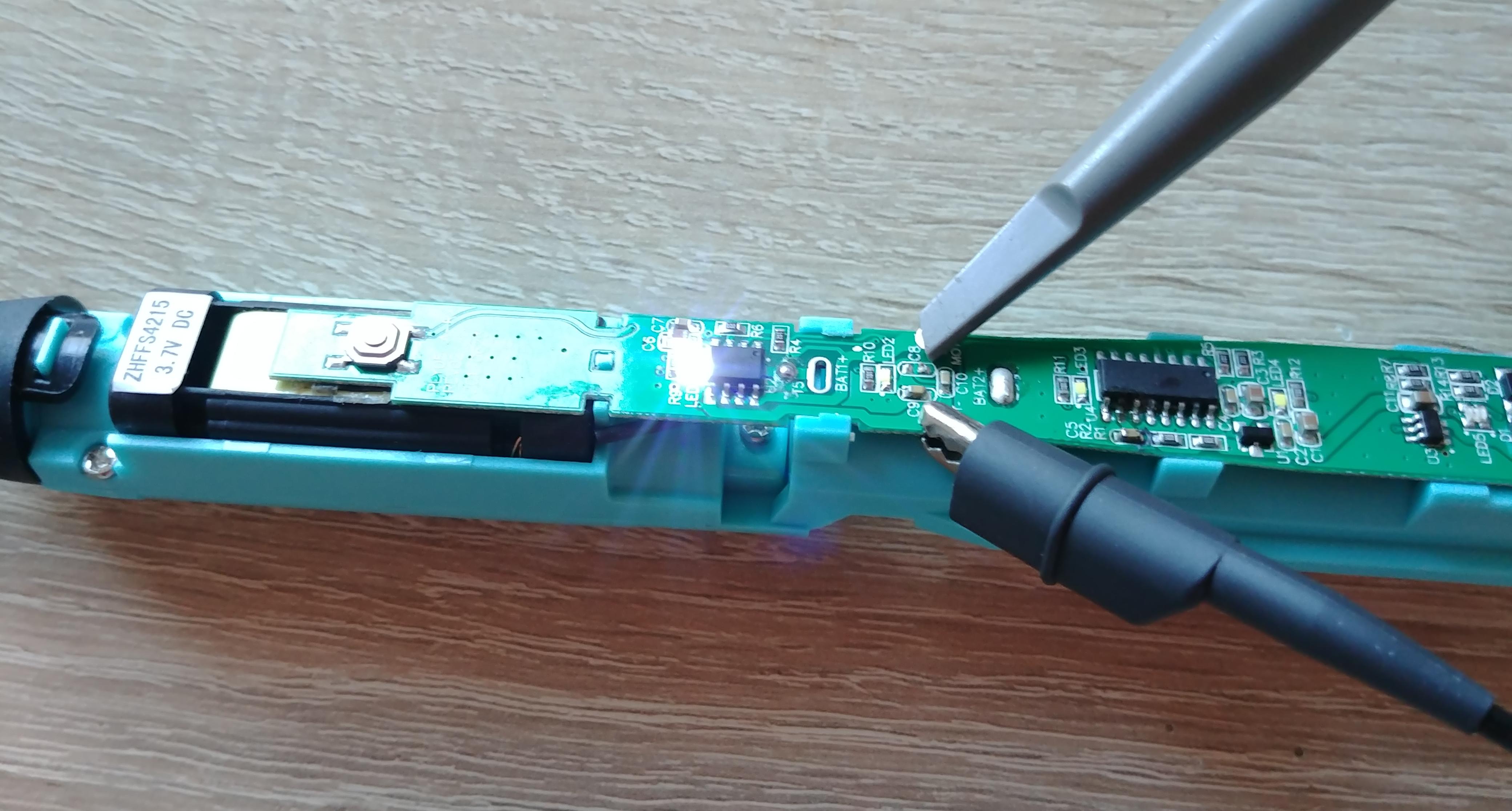
This is the normal program (1ms per division horizontal, 2V vertical):
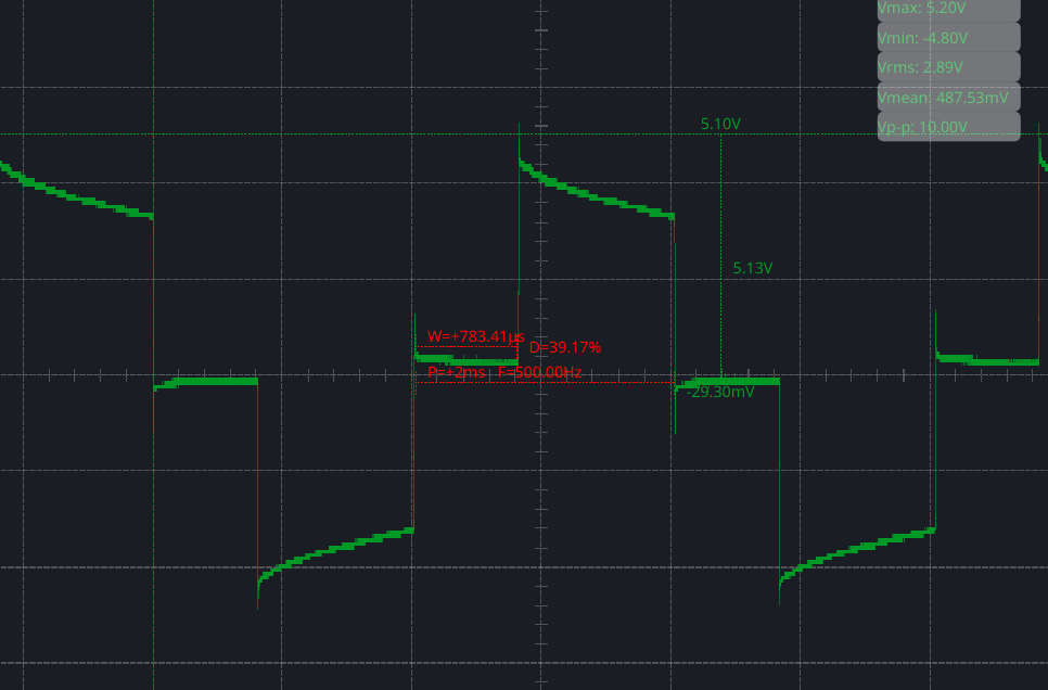 On the datasheet it has 30 000 vibrations per minute, that equals 500 Hz and i can confirm this here, a movement back and forth is obviously counted as 2 vibrations.
Seen as AC this would be just 250 Hz.
On the datasheet it has 30 000 vibrations per minute, that equals 500 Hz and i can confirm this here, a movement back and forth is obviously counted as 2 vibrations.
Seen as AC this would be just 250 Hz.
Following the softer “sensitive” mode:
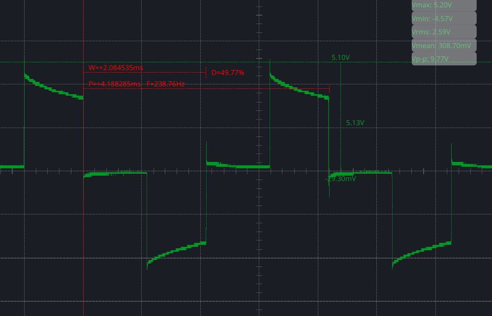 Both frequency and duty cycle gets a bit reduced.
Inductive charging is also included, i measured directly on the coil to find out the frequency here:
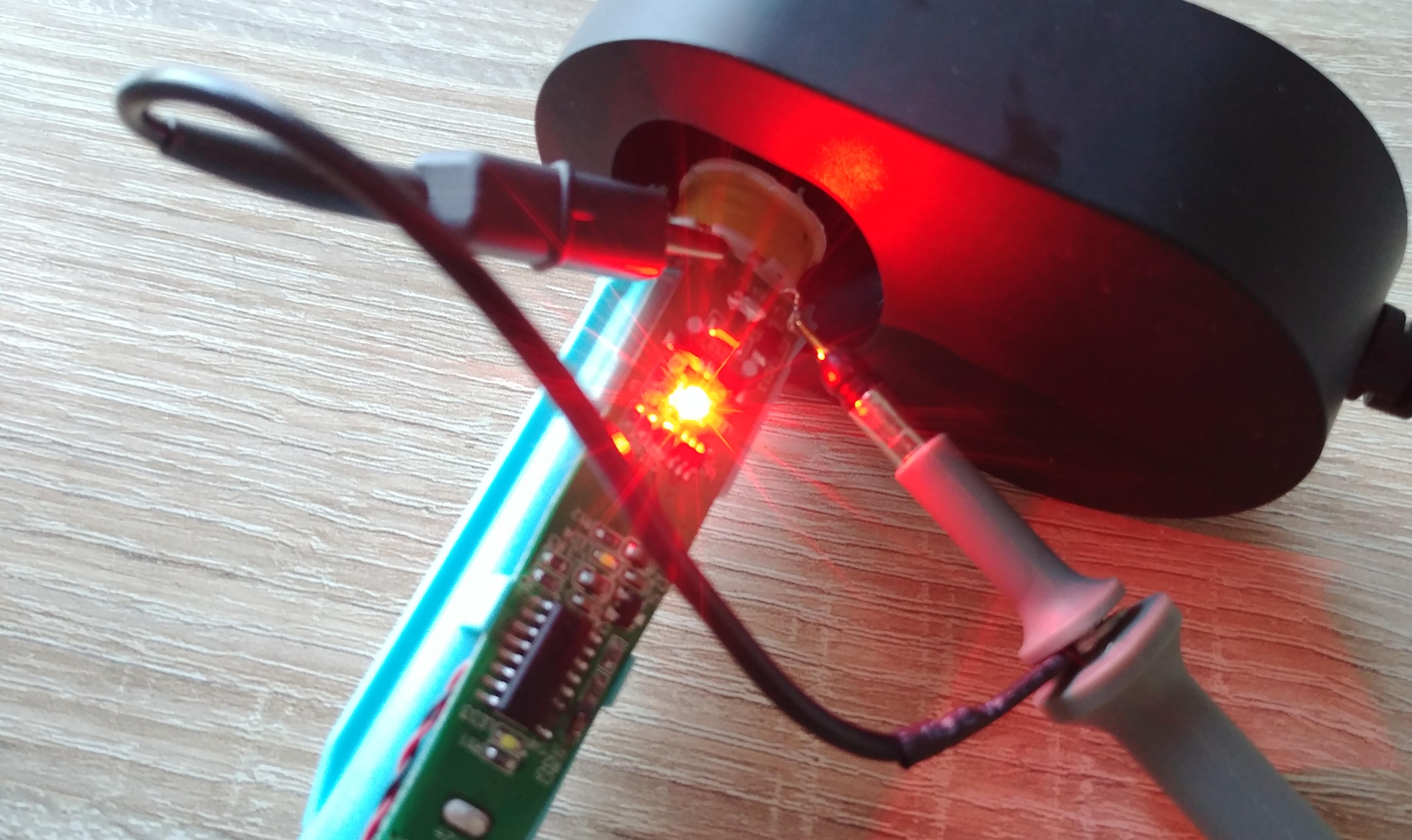 Resulting in 480 kHz and +/- 10V (20 Vpp), but it seems to use only the positve half cycle, which makes sense because one side of the coil is directly connected to the battery ground. Adding a full bridge rectifier could improve the efficency.
Assembly
Put the coil back on the holder and add the ferite core and foam piece on top. Then just slide it back into the outer case and put the bottom cover in again. Pretty simple.